![]()
Modifications for the TR-808
Sound mods, 4 Level Accent mods, 32 Banks of Memory and MIDI.
© Robin
Whittle, Real World Interfaces
Daylesford Victoria Australia
rw@firstpr.com.au 27 February 2020
(2020-02-27)
I have a backlog of Devil Fish work, in part because I have been
prioritising TR-808 work. For the first half of 2020 and perhaps
longer I will be prioritising Devil Fish work on TB-303s and TT-303 Bass Bots, so it may be some time before I accept more TR-606, TR-808 or TR-909 work.
prices-au/ Prices for Australian customers.
prices-int/ Prices for customers outside Australia.
To the Real
World Interfaces page, including links to TB-303, TR-606 and TR-909 modifications.
To
to the main
First Principles
site.
ABN 29 836 876
922.
TR-808s are extremely valuable - too valuable to send via Australia Post. Please see: ../freight-insurance
Jakub Matwiejew
(Audio Custom) in Poland does remarkable respray and screen print
refurbishment of synthesizer cases. (Jeff Toman in the UK used to
do this sort of work, but as far as I know he no longer does so.) In
January 2020 I am working on a TR-808, the metal front panel of which
he has completely refurbished by removing the original paint and
legends, removing all the rust, and then by respraying and screen
printing new legends in the three colours. While the orange
legends are not as bright as the original, and the yellow slightly
paler, in all other respects, the outcome is splendid.
I intend to have some photos of this work on a separate page here. Kuba (as he signs is name on his eBay account) seems to do most of his business via his Facebook page (link). He has a website https://www.audiocustom.pl, but there is no email address there and the contact form does not seem to work.
He makes white and orange inserts for the small knobs of the TR-808. So does this this company: https://www.ocsidance.com/product/roland-tr-808-potmeter-inlays/ . I haven't seen either of these in the flesh, so far.
Contents
| sounds/ |
Sound samples MP3, WAVs and via SoundCloud. |
| #32bankmem | 32 Bank Memory. |
| #dbs |
32 Bank Memory with 2 or 4 channels of Dynamic Bank Switching. |
| #4levelaccent |
4 Level Accent Mods. |
| #soundmods |
Sound Mods. |
| #midi |
MIDI In and Out, MIDI In and MIDI In Sync only. |
| #switches | Switch replacement, cleaning and various repairs. |
| #membak |
New battery arrangements for retaining memory data. |
| TR-808-switches/ | For technicians: notes on repairing or replacing TR-808 switches and pots, especially the Start / Stop and Tap switches. |
Sound Mods, 4 Level Accent Mods and 32 Banks or Memory
The 32 Bank Memory System is identical in principle to that for the Devil Fish:
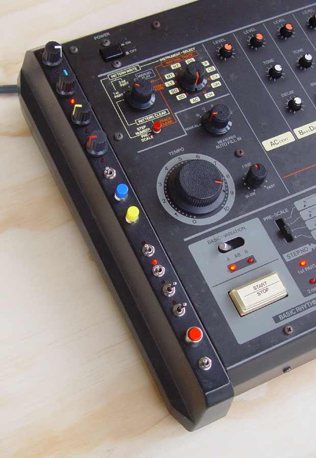
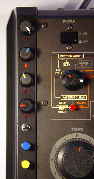
There are 5 toggle switches, moving side-to-side, and a pushbutton switch. These are located on the front left side panel. This provides 32 complete sets of the TR-808's original memory. The main purpose is not so much to provide more pattern and track memory, but to allow the switching of memory banks while the machine is playing patterns. The CPU reads from memory for each beat, so this enables switching to another pattern in the middle of a pattern rather than waiting for the current pattern to end. This means fresh notes can be dropped in with the flick of one or more switches.
The 32 banks are selected by the 32 combinations of the 5 toggle switches. The pushbutton reverses the bit produced by the front (bottom) toggle switch.
#dbs
This memory system is also available with a two or four channel Dynamic Bank Switching (DBS) system. This enables externally applied audio or CV signals, via 3.5mm sockets on the right side of the machine, to alter which of the 32 memory banks is selected. This means that the internal sequencer will play different patterns and one or more individual beats from different patterns in response to these signals.
Please see the Devil Fish 32 Bank Memory system with DBS manual, which also covers DBS for the TR-606 and TR-808: http://www.firstpr.com.au/rwi/dfish/DF-32-Bank-Mem-DBS-Manual.pdf
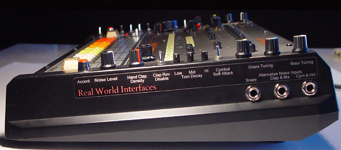
The 32 Bank Memory System is available with two or four channels of Dynamic Channel Switching: either two or four 3.5mm Audio/CV input sockets (each with a detector circuit and LED, with a threshold of about +1.15 volts) which, when activated, inverts the address bit produced by two or four of the four toggle switches which supply four of the five address bits to the 32 Bank system. They are mounted on the right panel, below the Noise Level pot and the Accent switch.
(In the 1980s I installed 11 and 21 bank memory systems, with bank selection via a thumb-wheel switch or pushbuttons and a 7-segment LED display. Information about these mods is at the end of this page: #older)
#DBS-switching-sockets-photo
Here is a photo of the right side of a machine I worked on in 2017, with the four 3.5mm input sockets for Audio/CV signals for four channels of Dynamic Bank Switching. The front-most input (left in this photo) drives a detector which can invert the address bit produced by the front-most memory toggle switch on the left panel (the toggle switch on the right, in the photo above - the one just to the left of the red push button switch). This photo also shows the similar Audio/CV input which turns on the Accent function, as part of the Sound Mods. (In this photo you can also see where I filled in holes previously used by the Kenton MIDI system, and the new locations of these sockets.)
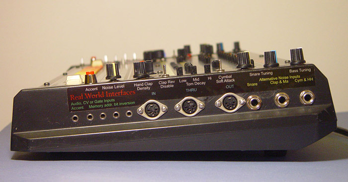
Here is a larger image showing the LED for the Accent Audio/CV input, above (to the right in this photo) of the Accent button: TR-808-Sound-Mods-with-Accent-LED-1900x1173.jpg
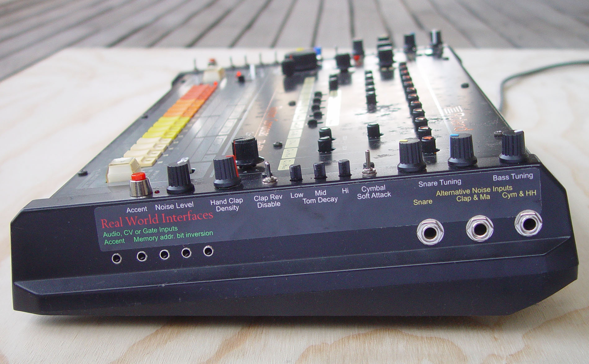
#DBS-switching-example
Below is a photo showing the 4 Level Accent mods (described next) and the 32 Bank Memory system controls, with the 4 LEDs indicating the state of the 4 Audio/CV input detectors, which when On, invert the address bit generated by the corresponding toggle switch.
In this example, with the switches producing 0 for left and 1 for right, the address bits are:
0 1110
which we can think of as bank 14 in the set of banks 0 to 31. The bits are numbered, left to right 4 3210 and are worth 16, 8, 4, 2 and 1 respectively. Working from the front (bottom of photo), for the left-most bit 4:
- The front switch is to the left and its 0 is not inverted by the red push button being pressed. There is no DBS inverter circuit for this bit 4.
- The next two toggle switches are to the right, so their bits 3 and 2 are 1 and 1. There is no inversion since their Audio/CV detectors have not been activated.
- The next toggle switch is to the left, which produces bit 1 as 0, and its Audio/CV detector has been activated, so its LED is on and the inverter turns the 0 into a 1.
- The final toggle switch for bit 0 is to the left, producing a 0. There is no inversion since its Audio/CV detector has not been activated.
If the signal which activated bit 1's detector falls below the detector's threshold, the LED will turn off, the bit will no longer be inverted and the bank from which the Internal Sequencer reads will be bank 12:
0 1100
 |
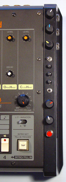
#4levelaccent The TR-808's drum circuits are triggered by pulses which start at 0 volts, rise to a certain voltage for 1 millisecond, and then fall to 0 volts again. The 4 Level Accent Mods enable normal operation of the Accent system (a 5 volt trigger pulse on non-accented notes with a 5 to 14 volt trigger pulse for accented notes) and a new mode of operation. In the new mode, the trigger voltage for triggering all the activated drum sounds on the current beat comes from one of four pots. One of these will be selected on each beat depending on whether the Accent and the Cowbell is programmed. Each such selection is signaled by a flash of the LED below the knob.
While playing a pattern, one of these LEDs flashes for every 1/16th note, and the setting of the corresponding pot determines the trigger voltage for all drums which are programmed on that beat. The range is between about 2 volts (fully anti-clockwise, about 8 o'clock) and 14 volts (fully clockwise, about 4 o'clock). The ~2 volt level is adjusted so it just triggers the drum sounds. (This mod also changes some internal circuitry to make the Cymbal and HiHat circuits have the same threshold of about 2 volts. Normally, they require about 4.5 volts before they will make a sound.) While the internal sequencer is playing a pattern (or being switched between patterns with the 32 Bank Memory System), the dynamics of the pattern can be completely altered by turning the four knobs. The toggle switch selects between normal and 4 Level Accent mode. The blue and yellow pushbuttons over-ride the Instrument Select switch so the TR-808's buttons and LEDs work with the Accent and Cowbell respectively, rather than whatever drum channel the Instrument Select switch selects. This makes it easier to program the desired Accent-Cowbell combination on any of the 16 beats. These 4 Level Accent mods are identical to what I installed in the early 1980s, except that I am now using slightly smaller knobs with metal-shaft pots. The earlier pots were not as robust as I would like. The User Manual is: TR-808-Four-Level-Accent-Mods.pdf The Hand Clap Trigger output will not activate on beats with a trigger voltage close to the minimum. This might be annoying but I think that in general it is more musically useful to have it this way than to add extra electronics to make the trigger output work irrespective of the trigger voltage. |
Please see sounds/ for some sound recordings in which I demonstrate the operation of the Sound Mods and the Four Level Accent system.
| #soundmods The Sound Modifications are an extension of what I first installed in the early 1980s, with new pots and knobs, three small pots for the Tom/Conga Decay function (instead of toggle switches and trimpots) and three additional functions marked * below. The User Manual TR-808-Sound-Mods.pdf contains the following description of features:
|
|
MIDI In and Out, MIDI In and MIDI In for Sync only
There are three approaches to MIDI interfacing the TR-808. The prices are at prices-au/#midi and prices-int/#midi .
The first and most comprehensive option is Kenton's MIDI In and Out system, for MIDI Sync and Notes, both in and out. The manual for this is available from the Manual tab of: http://www.kentonuk.com/products/items/sockets/roland/tr808.shtml Many TR-808s have this interface, or an earlier version of it, already installed. Alternatively, I can purchase a kit and install it, though this will take a while since the kits are made to order in the UK and there will be another week to ten days shipping. The Kenton interface has three 5 pin DIN sockets on the right panel. The original locations do not suit the Sound Mods, so as part of the Sound Mod work I relocate and label them as you can see in a photo above.
Here is a PDF TR-808-Kenton-MIDI-interactions.pdf describing the interactions between the Kenton interface and the Sound Mods, 32 Bank Memory system (potentially with Dynamic Bank Switching) and the 4 Level Accent system.
The second approach is the RWI MIDI In system for MIDI Sync and MIDI notes In only: TR-808-MIDI-In.pdf . This receives MIDI notes on Channel 10, though I can configure this to a different channel of your choice. The MIDI note numbers are mapped to drum channels according to General MIDI. I can configure these as you choose as well. (If you or your technician has an EPROM programmer, it is also possible to edit the firmware to alter the receive channel and note numbers.) In the list below, the entries in grey are additional note numbers to match similar drums in General MIDI.
C 1 36 BD Kick
C#1 37 RS Rimshot/Claves
D 1 38 SD Snare
D#1 39 HCP HandClap
E 1 40 SD Snare
F 1 41 LT Low Tom
F#1 42 CH Closed HiHat
G 1 43 LT Low Tom
G#1 44
A 1 45 MT Mid Tom
A#1 46 OH Open HiHat
B 1 47 MT Mid Tom
C 2 48 HT Hi Tom
C#2 49 CY Cymbal
D 2 50 HT Hi Tom
D#2 51 CY Cymbal
E 2 52 CY Cymbal
F 2 53
F#2 54
G 2 55
G#2 56 CB Cowbell
A 2 57
A#2 58
B 2 59
C 3 60
C#3 61
D 3 62 HT High Tom
D#3 63 MT Mid Tom
E 3 64 LT Low Tom
F 3 65
F#3 66
G 3 67
G#3 68
A 3 69
A#3 70 MA Maracas
B 3 71
C 4 72
C#4 73
D 4 74
D#4 75 RS Rimshot/Claves
E 4 76
F 4 77
F#4 78
G 4 79
G#4 80
A 4 81
A#4 82
B 4 83
C 5 84 AUX Auxiliary Trigger Out
The Auxiliary Trigger Out produces a 0 to 10 volt trigger pulse, according to the velocity of the MIDI note for C 5 (84). This might be used for driving various modular synthesis modules.
The third is the RWI MIDI Sync In only system as described here: TR-808-MIDI-Sync-In.pdf. It receives Sync in a similar manner to the RWI MIDI In system, and can use the Sync Lead in the same way.
Both these RWI systems can work with the optional Sync Lead: ../dfish/sync-lead/ to drive the DIN/Roland Sync signals created by the interface from incoming MIDI Sync messages, to one, two or three slave devices, such as other TR-808s, TR-606s or TB-303s. If three is not enough, we can make Sync Leads with more plugs for slave devices.
Here is a chart depicting the major distinctions between these three approaches to MIDI. For the full details, please refer to the above-linked PDFs and the Kenton manual.
In and Out Sync only
MIDI Sync In Y Y Y
MIDI Notes In Y Y
MIDI Sync Out Y
MIDI Notes Out Y
MIDI In } 3 separate Sync socket Sync socket
MIDI Thru } sockets
MIDI Out }
Channel & note Y
numbers can
be altered
Separate MIDI Y
In note numbers
for HCP and MA
Needs Sync Y Y
Lead to drive
Sync slaves
HCP Trigger Y
Out driven
by MIDI notes
Aux Trigger Y
output 0 to
10 volts
#switches
Switch replacement and various repairs
TR-808s are now about 37+ years old. They typically require some cleaning and fixing as part of doing any modifications.
TR-808s use ALPS tact switches which are open to dust. I replace them with sealed Omron tact switches which have a similar feel. Since these are sealed against dust and liquids I expect they will last a very long time, such as decades, rather than the few years it typically takes for the unsealed ALPS switches to become erratic.
I fix Volume pot noise problems by dismantling it and cleaning it with isopropyl alcohol. The 22 small pots (without knobs) sometimes become noisy. I clean them in-situ with isopropyl alcohol and compressed air. Likewise the prescale slide switch, the Tom/Conga slide switches, the two left-right toggle switches and the Tempo and Fine pots.
The output sockets and small red pushbutton switch have not, in my experience, given any trouble. In 37 years of working on TR-808s, TB-303s and TR-606s, I never observed a failure in the rotary switches . . . until one was flaky in a TR-808 in late 2018. This is a very good reliability record. The key-switches for Run/Stop and Tap are prone to failure. I have a fairly involved method of repairing them, but ideally there would be replacements for these which were less prone to failure. I have used a set of replacement switches with matching 3D printed buttons from Social Entropy.com, with great success. However, these are no longer available. Thanks to the sleuthing efforts of some people who collect Cherry key switches, I should soon (by mid March 2019) have some new old stock Cherry key switches which can be adapted to take the place of the original key switches. These should prove to be highly reliable, since they have metal-to-metal contacts, while the originals relied on conductive rubber, which can degrade and rendered non-conductive by oil and solvents.
I have developed self-adhesive laminated replacement orange labels for the START / STOP and TAP buttons to replace those which may have been lost, including if the top plastic cover is missing.
The black random-weave dust covers around the shafts of the slide and toggle switches may become ratty after a few decades. I can replace these with similar shaped covers cut from a black shiny woven fabric used for BBQ hotplate liners. These should last for centuries.
There is a fault in all TR-808s which corrupts the first pattern and the first track. It is caused by capacitive coupling of turn-off inductive transients from the power transformer into the write-enable signal for the memory system. I fix this with a simple low pass filter at the memory and by tying the line inactive-high when the Mode Selector is in the 1st Part or 2nd Part positions. (Technicians: the details of this mod are described in the TR-808-Memory-Backup.pdf file linked to below.)
Some TR-808s have corrosion on their right-hand circuit-board (Cowbell, Cymbal and Hi Hat). This appears to arise from contamination in the factory, and can develop over decades into potentially severe corrosion of parts of the circuit board and its components. This is rare and not disastrous, but a bad case can take several hours to fix.
I can install back-to-back high-current diodes in the ground lead so that there is a 0.5 volt float between the ground pin of the mains cable (assuming it is a three pin power plug) and the chassis and ground of the TR-808. This will eliminate various ground noise problems which might otherwise be caused in some circumstances.
Some people in 220-240 volt countries such as Australia (230 volts) have a TR-808 which was built for the Japanese market (2 pin power cord and 100 volt power transformer) of for the North American market, with a 115 volt power transformer. I can install a toroidal power transformer and make some changes to the internal power supply so that the machine runs on 230 or 240 volts. The toroidal transformers I have used since 2018 have two windings in series, so they can be rewired in parallel to run on 100 to 120 volts. If anyone from a 100V to 120V country has a 220V to 240V TR-808, I may be able to transplant an older power transformer to make it operate from the lower mains voltage. Some of these original 100 to 115 volt transformers buzz a little, but the new toroidal transformer has no mechanical buzz whatsoever.
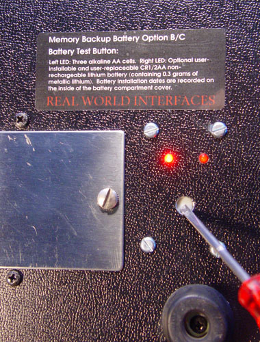
#membak
New Battery Arrangements for Retaining Memory Data
This is a separate set of modifications for the TR-808, whether or
not
the machine has a 32 Bank Memory system installed. (With the
TB-303, the new memory backup battery arrangements are part of the
Devil Fish
mods.) The purpose is to provide a more robust and convenient
backup power system for the memory
system than is possible with the original arrangements, which involve
three AA batteries in the battery compartment in the bottom panel.
Prior to May 2015, I offered an optional memory powering system
involving a
permanently installed (soldered connections) large capacity,
"1/2 AA" cylindrical lithium battery. In 2015, due to
restrictions on
air-freight carriage of items including lithium batteries, I developed
an alternative due to Australia Post regulations which prohibited
shipping packages containing such batteries. In 2017, the
Australia Post regulations do
allow the carriage of instruments with these lithium metal batteries
via their EMS service, which is currently known as "International
Express". (This is not true of the "International Courier"
service.)
For the full
details of the original arrangement (option A, a permanently
installed lithium battery) and the two new Options B (new circuitry
with no lithium battery, but a battery holder for such a battery) and C
(new circuitry with the user-replaceable lithium battery installed in its holder) please see the PDF manual: TR-808-Memory-Backup.pdf . (For a version of this document from 2015, which applies to a few machines modified before September 2017, please see: TR-808-Memory-Backup-2015-10-20.pdf . This was written on the basis of us not being able to ship with Australia Post any machine with a lithium battery installed.)
For both Options B and C, the three AA cells (it is best to install
only alkaline cells) can still be used to provide backup power to
the memory system. A large capacitor
enables the machine to retain memory contents for a longer period than
usual without these three AA batteries and without the machine being
run from an
external power supply. There is an internal holder for a
cylindrical "1/2 AA" lithium battery, which can be accessed by
removing the right part of the case. This is the same type of
battery we have been using in Devil Fishes, TR-808s and TR-606s since
1996, except that it is the version without leads, so it clips
directly into a suitable battery holder.
With the 1/2 AA lithium battery in this holder, there is no need for AA alkaline
batteries. The lithium battery should last for ten or more years.
This modification includes a recessed switch and two LEDs which test the charge and connectivity of both the three AA alkaline batteries (if any are installed) and the 1/2 AA lithium battery (if this is installed):
This modification is not essential, since the three AA alkaline battery
arrangements are generally reliable, provided fresh alkaline batteries
are installed every few years, and there is no corrosion or other
problems with the battery holder for these. It is a desirable
modification for anyone who wants a reliable memory, since the AA cells
and their six battery holder contacts are less than 100%
reliable. (If you use AA cells, be sure to insert adequate
packing between them and the battery compartment door, since the light
foam there - if it still exists - is typically too soft, to hold the
batteries in their holder.)
This
modification provides an easy way of testing the
voltage and connectivity of the three AA batteries, if any are
installed, and the internal lithium battery, if one is installed in the
holder.
For customers in Australia and overseas, we ship the machine with the lithium
battery installed, but we do not install new AA alkaline batteries,
since these are not needed once the lithium battery is installed.
#prices
Prices
prices-int/ Prices for customers outside Australia.
I have not included a price for installing new LEDs - the A, B, 1st Part and 2nd Part LEDs and the 16 LEDs in the Step buttons. I can do it, but it is inordinately difficult to install new LEDs in the Step buttons, even when I am removing the buttons to replace the tact switches. The original Red LEDs are fine and I recommend leaving them as they are.
#older
Documentation for older modifications
From about 1982 onwards, I worked on a few dozen TR-808s, which can now sometimes be found for sale on eBay. All these were for Australian customers, but some may now be in other countries. The mods are:
- Extra memory banks with two types of control system:
- The first ones had 10 or 20 extra banks and had a thumb-wheel
switch to select the banks with 0 to 4 or 0 to 9. There were 5 or
10 new banks accessible when a three position toggle switch was in the
left position, the original bank of memory was accessible with the
middle position and 5 or 10 new banks of memory were accessible via the
right position. Changing the memory bank, by number or the
left-mid-right switch would normally reset the CPU, so the sequencer
firmware didn't get confused about pattern lengths and in track
mode. This was for people playing large numbers of songs, not
primarily for live switching between patterns in different banks.
However, the CPU reset could be disabled so the user could switch
between memory banks while the patterns were playing. There was
also a write-protect switch. (On one or more machines I may have
done the CPU reset with a pushbutton, so changing bank would not reset
the CPU at all.)
- The second and more common type had the same arrangement of
memory banks, but I replaced the thumb-wheel switch with two
push-buttons and a 7 segment LED display. See documentation below.
- Sound controls. As described above except for the items
with an asterisk and with different arrangements for the Alternative
Noise Inputs.
- Four level Accent system, as described above.
This is the manual for the original ca.1995 MIDI In system, with full velocity control of each drum channel, an extra 0 to 10 volt velocity sensitive trigger output and Sync reception.