A DIY Audio Patchbay made from a Solderless Breadboard
2009-01-29
Robin Whittle rw@firstpr.com.au
To other things I made: ../ To the Devil Fish page: ../../rwi/dfish/ .
Minor update 2009-10-02: See Jeff Jonas' page http://ferretronix.com/stuff/breadboards/ on the history of these breadboards from a company which changed its name from Elenco Precision to Continental Specialties and then to Global Specialties. These prototyping boards are such wonderful things. See the directory here Continental-Specialties/ for some photos, including of a 1976 standalone unit, with powersupply, called the CSC Design Mate 1.
This is how I made a patchbay in the early
1980s for linking together tape recorders, drum machines, synthesizers,
reverb units etc. There was a discussion about how to make
patchbays on the Synth DIY list (
http://dropmix.xs4all.nl/mailman/listinfo/synth-diy)
in late January 2009.
"Solderless Breadboard" or "Solderless
Bread Board" seems to be the best term for these things now. At
the time I made this, the initial and perhaps only manufacturer was a
US outfit called "Continental Specialties" and the strips were known as
"QT Strip". This was in the mid-70s - and Googling the term now
turns up nothing. Ahh - I see the company changed its name
to "Global Specialties". Googling this with "Proto-Board"
turns up some products . . . yes - they are still in business:
http://www.globalspecialties.com/proto_accessories.html
. Indeed the very same QT Strips I used are still available:
http://www.globalspecialties.com/qt59s.html
.
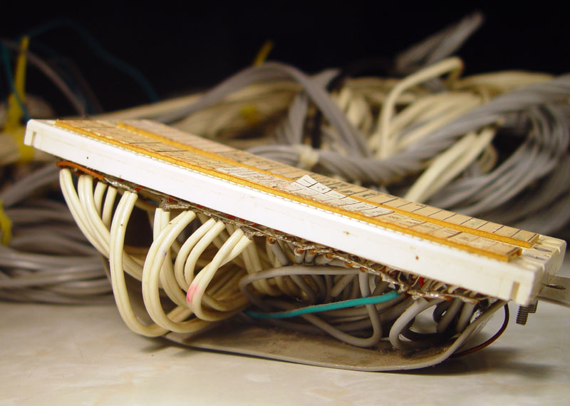
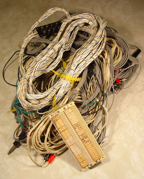
I haven't used this for years, since I am currently not set up
for making music with a bunch of gear. It has been in a box, and
looks worse for wear:
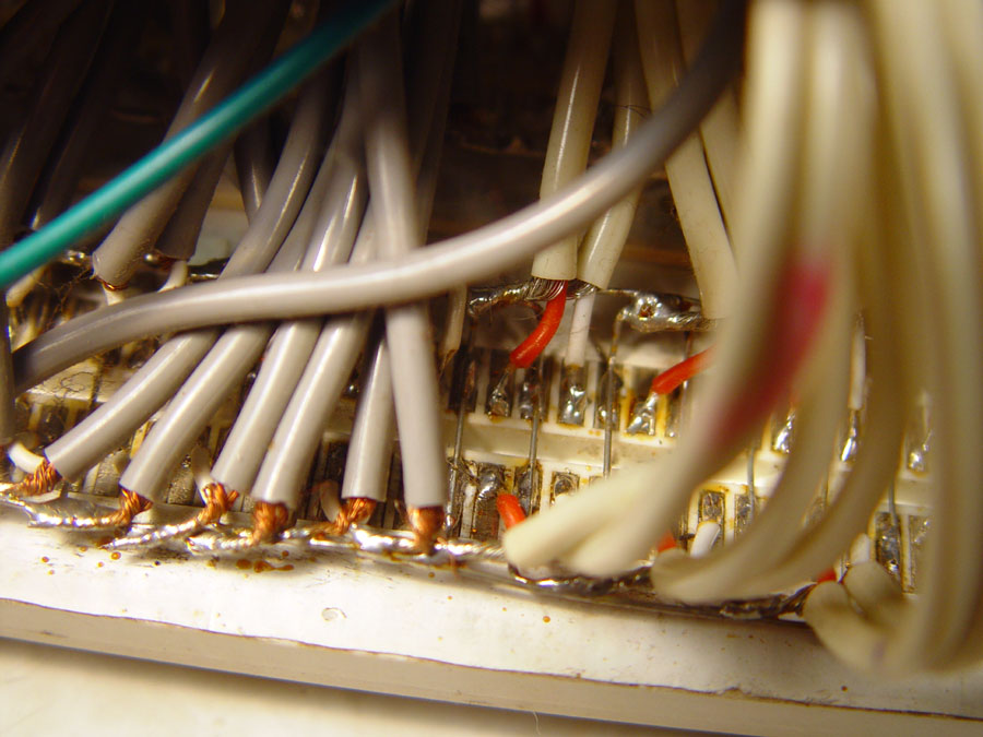
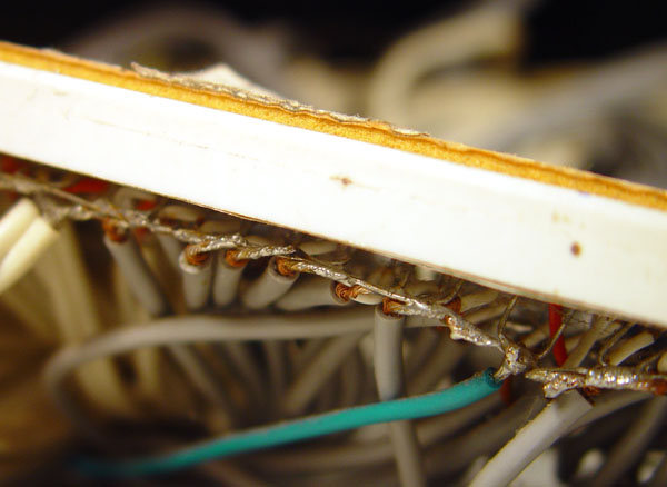
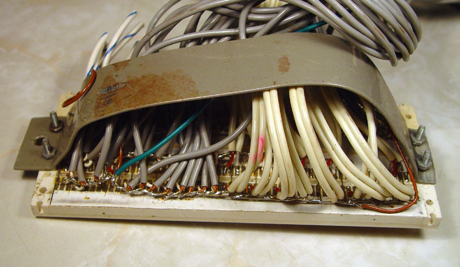
I removed some of the plastic insulation on
the back. Then I soldered to the back of the metal
connectors. Every second connector is ground. This stops
capacitive coupling from one signal to the next.
Soldering is tricky, since it was easy to melt the plastic.
I may have run a file or some abrasive paper down the area I was
going to solder, to make it easier to solder. (Don't try this
with leadless solder - it is too hot and does not wet as nicely as real
solder.)
For a description of what is inside these protoboards:
http://www.ece.rice.edu/~jdw/242/breadboard.html
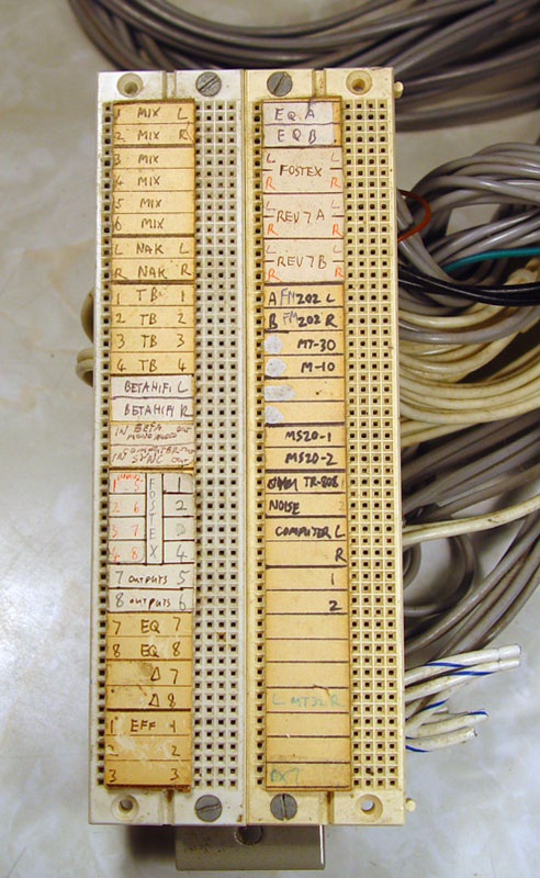
Every other connector on the left was an input of
some device and on the right I had the outputs of some device,
usually the same as whatever was on the left.
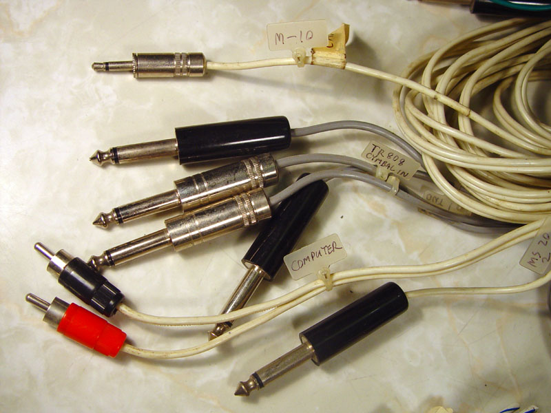
I soldered
the shielded wires directly to the back of the QT strip. The
shielded wires went out to the appropriate connector for the
device. So it was the centre of the studio, with cables branching
out all over the place.
Connections to patch things together were
simply made with single strand "bell wire". It is also possible
to get fancy connector leads with flexible wire:
There was no shielding of the actual
jumper leads. None is required since these are all nice strong
"line level" signals - low impedance output and with a high signal
level.
I had a strip of double-sided foam-backed tape
down the middle where I had stickers to label the connections.
This limits the number of holes which can be used, so I allowed only
one hole on the left, since this was the input. This left four
holes on the right for each output.
This system worked like a charm.
I never had a problem with crosstalk or a bad connection.
I
used it for many years, and if I was building another studio I would
probably do it the same way - except for these pesky cable nylon
labels, which kept tangling other cables.
~~~ooo000ooo~~~