Devil Fish
mods
to the TB-303
TB-303 maintenance and simple modifications
2013-11-24 Robin Whittle
rw@firstpr.com.au
Here are some modifications and maintenance tips. Please
also
see the notes on spare parts in Q9 of the FAQ at the main Devil Fish
page.
To the main Devil Fish page.
An update history is at the end: #updates
.
This
information is for
people who already know about electronics and in particular about
avoiding static electricity damage to electronic equipment. If
you don't already know about static electricity and if you did not already know that it
can destroy components - including the CPU of the TB-303, for which
there is no replacement - then please get a competent technician to
work on your machine rather than doing it yourself.
Search engine bait: TB303 pots, TB-303 pots, TB 303 pots,
Bassline
pots, TB303 switches, TB-303 switches, TB 303 switches, Bassline
switches.
Contents
1 - Replacing the
tact switches with Omron B3W-4050 sealed tact switches
2 - Six small pots from Tuning to Accent
3.1 - Never spray anything in the machine
3.2 - Overheated Q45 power transistor
3.3 - Pinched wires during re-assembly
3.4 - Knobs falling off
3.5 - Noisy volume pot
3.6 - Batteries not connecting
3.7 - Memory problems - corrosion of RAM chip pins
3.8 - Buzzing due to LED activity
4.1 - Increasing the range of the Cut Off and Env
Mod pots
4.2 - Improving the bass response
Update history
1 - Replacing the tact
switches with Omron B3W-4050 sealed tact switches
#Omron_switches
These notes apply to the TB-303 and TR-606, but there are
also some
notes on similar switches which are used in the TR-808, JP-8 and the
original DX-7.
Please see ../tact-switches/ for
a comparison between the original ALPS unsealed tact switches, the
ALPS sealed tact switches and the Omron sealed tact switches.
The TB-303 has 24 "tact" (tactile) switches which were made by the
Japanese
company ALPS http://www.alps.com
who make the pots and rotary switches in the TB-303 and the miniature
pots
in the Devil Fish. These are good switches, but they are not sealed
against
dust.
Household dust, especially flakes of skin, get into the switch and
contaminate
the contacts, causing them to become unreliable. This can make the
TB-303
impossible to program. The original DX7 uses the same switches as
the TB-303 / TR-606.
However, they seem to last very well in the DX7, where they are well
protected from dust.
Until mid-2010 I replaced these switches with the same type, which
by 2010 were known as SKHCBEA010, but which were originally known as
SKHCAA. To protect the switches from dust, I installed a thin
plastic dust guard which covered the switches, but had holes for their
stems and for the nearby LEDs. This worked very well, but not
perfectly. Some machines which were used intensively needed their
switches replacing again after about 10 years.
One alternative is to use ALPS sealed tact switches:
SKQEAAA010. Based on my experience with 100 of these I ordered from the ALPS distributor here: http://www.switchesplus.com.au
I decided not to use these, because I found their click action to be
much weaker than that of the original ALPS unsealed switches and of the
Omron sealed switches. Please see the above-mentioned comparison
page for details
The only other suitable sealed tact switch I am aware of is the
Omron B3W-4050. Omron,
like ALPS, is a very highly respected
Japanese manufacturer. The Omron tact switch page had a very long
and perhaps not very permanent URL
in August 2010. Likewise the PDF datasheet, so I have archived a
copy of it
here: Omron-Tact-Switches-2010-B3W_1109.pdf
.
The
B3W-4050 has a stem almost like the original ALPS switches,
but the stem is unfortunately too wide for the TB-303 / TR-606
switches. (It is specified to be the same size: 3.8mm.
However, in reality it is too wide.) To replace the stemless switches
(originally known as
SKHCAB) in the TR-808 or JP-8 the B3W-4000 switch
would be one to use.
These Omron switches are available from Farnell / Newark. In
mid-2010, the Australian Farnell system had two entries for the
B3W-4050. One was for Australian stock and the other was for US
stock from Newark - with the Newark switches prices being about 1/3 of
the Australian stock's prices. The Farnell number for the
Newark-stocked switches is1436527. The Australian page
has an image of another type of tact switch.
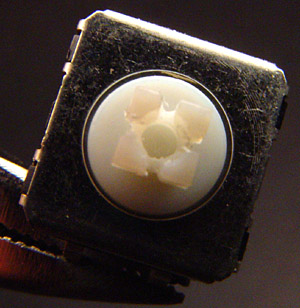
Modifying the Omron switches
The Omron switch stems are too wide for the TB-303 buttons. One
approach is to file them down - but this is very difficult, since the
stems are made from nylon or something similarly resistant to
filing. Another is to use a small, fine, but very fast grinding
wheel to shave a little off the four sides of the top of the
stem. Initially, this is what I did. I built a fancy jig to
enable me to do it reasonably reliably, but still I found it very
difficult to get the final dimensions correct. Doing this, it is
important to shave evenly, otherwise the button will be rotated
clockwise or anti-clockwise. I had quite a few rejects.
Part of the problem is that the holes in the TB-303 buttons vary
considerably. This may be partly due to molding differences, but
I suspect the main cause of variation is the different thicknesses of
copper plating underneath the chrome plating.
(By the way, the chrome plating on these buttons and knobs is
absolutely first-class. Many of these buttons and knobs have been
in frequent use for nearly 3 decades now, and are showing little or no
sign of wear. I don't know of any other button or knob which
lasts so long, and looks so good, no matter how much it is used.)
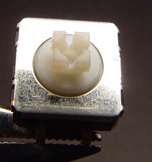
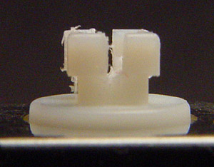
The solution is to cut the stem twice, at right-angles. This
doesn't reduce its outer dimensions, but makes it springy. There
are several advantages to this over trying to shave down the sides of
the stems:
- The cuts are non-critical in terms of thickness and
placement. Only the depth needs to be tightly controlled - just
to the bottom of the outer part of the stem, and not any further into
the neck of the stem. Shaving the sides down is extremely
critical, and requires even removal of about 25 microns from all 4
sides. This is thinner than human hair. The stems of the
ALPS switches are about 3.775mm and the stems of the Omron switches are
about 8.820mm.
- The cuts don't alter the outside of the top of the stem, so
there is no alteration of the button's rotational orientation on the
stem.
- The springiness which the cuts introduce into the stem makes
the stem fit very nicely into TB-303 buttons no matter what size their
holes.
It suffices to cut the Omron switch
stems by hand, with a Dremel tool or similar, with a 0.6mm cutting
disc. (The old Dremel cutting discs are a dull red or brown
colour.) It would be best to allow for some rejects with this
hand-held approach.
I adapted my original jig to do the cutting. I use a tiny metal
circular saw, with appropriate safety guards. If you already have
the Dremel saw attachment, that might be OK to use. Otherwise, I
suggest using a cutting wheel.
It takes me longer to remove the swarf from the cuts than to actually
make the cuts. I do this with a scalpel under a stereo
microscope. It is not necessary to remove all the swarf, since as
long as it remains attached inside the button, it can't do any
harm. Still, I try to remove the main pieces of swarf from the
two cuts. Most of the swarf is still attached because the plastic
partially melts during cutting.
Here are some photos:
Hopefully you will be able to obtain
Omron switches and cut them like
this. However, please see the Devil Fish page:
../#tact_switch_kits if you want to
purchase modified Omron switches from us.
Removing the old switches
When you dismantle the machine, you may want to keep it connected to
the
batteries (taped into its battery compartment) in order to retain the
memory
contents. Often the on-board capacitor will retain memory data for
days,
but it is probably best not to trust it when you are working on the
machine.
I suggest removing the buttons before desoldering the
switches. This can be tricky - I use very long pointy-nose pliers
to prise the buttons up evenly.
De-soldering the old switches is pretty straightforward. I use a
Weller vacuum de-soldering
station.
A second alternative is a standard soldering iron and a push-in,
press-to-release
solder sucker. The only problem with these is that the sucker may jump
forward
and damage tracks. A third alternative is to use solder-wick to soak up
the
excess solder.
Installing the new switches
This is easy – just solder them in.
2 - Replacing the 6 small pots from Tuning to Accent
#6_small-pots
Update 2013-11-24:
The pots described below are
not the ones currently being supplied by Technology Transplant.
They are now supplying the same pots which are used in the Cyclone
Analogic TT-303 Bass Bot. These pots are similar to those
described below, but their base is higher so the shaft height above the
PCB is correct. I don't know of any problems with the Resonance
pots becoming noisy in Bass Bots, so as far as I know these pots can be
used as they are supplied.
Soldering TB-303 and TR-606 pots is tricky. Once they are soldered in and the machine is ready to be reassembled, be prepared to heat the melt the joints and push the pots around a little so the shaft is close to the centre of the front panel hole.
Please see the page ../pot-wear/
for photos of how the original ALPS pots can fail due to being
turned while downwards pressure is applied to the shafts. This
causes the outside of the rotor to cut into the conductive
tracks. Earlier generation replacement pots from Technology
Transplant could fail in the same way.
In late 2009, Technology Transplant
http://www.technologytransplant.com
started selling another batch of
pots, which I think was their third or fourth batch. The first
one or two batches (the first was in 2002s, I recall) were dull zinc
plated.
The next batch (mid 2000s) was
yellow cadmium plated, and quite hard to solder. The cadmium
plated batch had a difficulty with the Resonance pot shaft being too
large for TB-303 knobs, so it was necessary to drill out the
knob. These Resonance pots were not linear - they had a log curve
at both ends. This is a minor problem, since it doesn't alter the
range of sounds, just which knob positions the sounds occur at.
Most of the pots in this cadmium plated batch, and I think most of
those in the earlier zinc plated batches, were also subject to the
problem of downwards pressure while turning causing the rotor to cut
into the conductive tracks. This was due to the design of the
pots which involved downwards pressure being taken by the outer part of
the rotor - so it id a design fault in the ALPS pots and most of the
earlier batches of TT replacement pots..
The late 2009, early 2010 batch of pots from Technology Transplant, as
pictured here:
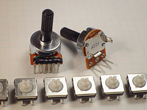
is completely different from earlier batches and from the original ALPS
pots. These are bluish silvery plated and very easy to
solder. They are 17mm in diameter, which is marginally wider than
all the other types of pots - but this size is fine, they are not too
big.
The good news is:
- The shafts of all the pots
fit the knobs perfectly.
- None
of the pots are subject
to the failure mode of the rotor cutting the conductive tracks if the
shaft is turned while downwards pressure is applied. This was the
primary mode of failure of the ALPS pots. In these new pots, the
downwards pressure on the shaft is taken by the very end of the shaft,
which goes through a small hole in the phenolic board, and presses
against the steel back-plate - about in the middle of the "A50K" text
in the image above. This means the outer part of the rotor never
goes near the conductive tracks.
Here is a photo of the rotor and
phenolic board of the Resonance pot:
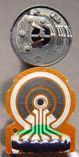
The central part of the shaft goes through the hole in the middle and
presses against the metal backplate. This takes all the downward
force applied to the shaft. The outer part of the rotor is not
close to the phenolic board, so it can never press against it or cut
the conductive tracks.
The black epoxy is to protect the riveted connections between the
conductive tracks and the terminal pins from corrosion.
There
are two remaining problems:
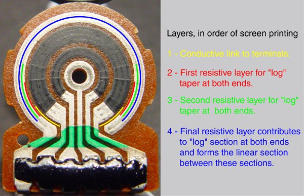
- The Resonance pot still has
the log curve at each end, rather than being linear. As noted above,
this nothing to worry about, since it just alters the knob
position for a given sound, rather than alters the sounds which are
available.
The photo below shows how the three resistive layers are printed, for
both sections of this dual pot.
- The shafts are about 1.6mm too
short. See the discussion below about what to do about
this. The
knobs on a TB-303 are already marginally too low. I have been
boosting
them up about 1.6mm for quite a few years. That technique - a
small
circle of leather inside the knob - could be applied to these pots to
restore the knobs to the original height, but it is not possible to
extend this technique to more than about 1.6mm.
I
understand that later in 2010,
Technology Transplant will have another batch of pots which solve the
shaft length problem by having an extended frame at the bottom.
This
should work fine.
In the mean-time, from August 2010 onwards, I am using the above pots,
with their shorter shafts, and boosting their mounting position with
some 1.6mm thick phenolic paperboard spacers I had laser cut.
We are very fortunate that Technology
Transplant has these pots manufactured, and sells them
world-wide.
This is an obscure pot-shape, and ALPS haven't made this kind of pot
since the early 1980s.
The values of the pots are:
- Tuning: 50K B (Linear).
- Cut Off: 50K A (Logarithmic curve on anticlockwise end).
- Resonance: Dual 50K B (Should be linear, but replacement pots
have a log curve at both ends).
- Env Mod: 50K A (Logarithmic curve on anticlockwise end).
- Decay: 50K A (Logarithmic curve on anticlockwise end).
- Accent: 50K B (Linear).
The original parts are no-doubt unobtainable, but here are the Roland
part numbers anyway:
- Tuning and Accent pots: 50K linear
(Marked
underneath
as
"50KB"). Roland part number 13219331.
- Cut Off and Env Mod pots: 50K log ("50KA"). Roland
part
number
13219340.
- Resonance pot: Dual 50K linear ("50KBX2").
Roland
part number
13219775 (not the 13219774 mentioned in the service
manual).
- Decay pot. 1 meg linear ("1MA").
Roland part
number
13219339.
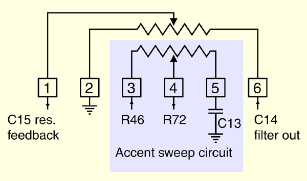
To help with debugging, the
following diagram shows the connections and function of the Resonance
pot:
3 - General maintenance
Here are a few tips on keeping your TB-303 healthy, and in reassembling
it.
3.1 - Never spray anything in the machine
Do not under any circumstances spray anything, such as WD-40,
contact
cleaner etc. into any item of electronic apparatus.
If pure water gets into the machine, due to rain or some other
source,
just let it dry. If there is lots of water, pull it apart and mop
it
up with tissues before letting it dry in warm air. The ALPS 24 tact
switches
will
not like being immersed in anything – but they may survive
water.
But how could they dry properly, since the actuator is closed against
the
retaining ring except when it is pressed? (Omron tact switches
are supposed to be sealed against liquid and dust, so they should not
be affected by liquids, unless they contain sugar and so gum up the
movement of the plunger.)
If some sticky liquid gets
into a machine, open it up and wash it away with warm water, using a
toothbrush
and maybe just a little detergent. Then let it dry in warm
air.
Best replace the ALPS tact switches!
3.2 - Overheated Q45 power transistor
Sometimes, presumably due to application of more than 9 volts, the
power
transistor Q45 may be brown or defective. I replace them with a
relatively
common PNP transistor called a TIP30. (Farnell
Electronic Components
has them). Whatever you use, make sure it has
the
pin functions, left to right, of Base, Collector and Emitter. The
TIP30 has the same connections. The TIP30's beta (hFE, AKA
current gain) may not
be as good as the original 2SB596 transistor. The TIP30A spec
sheet from Multicomp from Farnell quotes minimum beta of 40 for 0.2A at
4 volts VCE. However the minimum is only 15 for 1A at 4 volts
VCE. The 2SB596 datasheet from:
http://www.ortodoxism.ro/datasheets/WINGS/2SB596.pdf quotes a minimum
beta of 40 for 1A with 5V VCE.
I picked those transistors which required
less than1.5mA and put a 2.2k across R167, to boost the base current at
lower voltages.
The
Devil Fish requires more power than the TB-303, due to the MIDI In
system, the other circuitry and the three LEDs in the Devil Fish panel,
and for MIDI, the Blue LED too. The 1.5k R167 would
only have about 2.4 volts across it - 1.6mA (assuming there was no
voltage drop in R168 and Q44) when the input voltage is 9 volts.
Actually, this is the voltage with 9.5 volts going into the
machine and with R168 shorted and 1K across R169 (Devil Fish 4.0C and
later). So without these mods and with a genuinely 9 volt supply,
the voltage across R167 would be more like 1.5 volts and the base
current only about 1mA. We need a transistor with a beta of 180
or more when running with a collector current of about 180mA .
I
tested a batch of MOSPEC TIP30As to see what base current I
needed to get 200mA Ic with about a 4 volt VCE. The best was
1.02mA and the worst was 3.58mA. The 2SB596 needed 0.94mA, which
is a beta of over 200.
3.3 - Pinched wires during re-assembly
It is very easy to pinch various wires when re-assembling the machine –
especially
black wire 28 near the output socket. Replace any wires which have been
pinched
and exercise care when re-assembling
The Devil Fish has many more
wires. If you dismantle one, please be very careful re-assembling
it.
3.4 - Knobs falling off
A little piece of "Blu-Tack" (grey
putty-like stuff for putting posters on walls and a vast array of other
crucial tasks:
http://en.wikipedia.org/wiki/Blu-Tack
) is the best solution I have found. Never glue the knobs in
place. They must be removed for installation and maintenance of
the Devil Fish.
Keep an eye out for loose nuts on the tempo and volume pots.
I find that the shafts of the two rotary switches can vary somewhat. If
you take off their knobs, it is best to mark them so they can be placed
back on the same switch. The same applies to the Tempo and Volume
pots, which have very different shafts.
3.5 - Noisy volume pot
The original ALPS volume pots, with
integral power switch, rarely fail. However, over the years, they
can become noisy when turned.
I fix this by desoldering the pot and prising the back off it, by
bending back four lugs which wrap around the front face of the
pot. Then I clean the conductive tracks and the wipers -
especially the two inner wipers to the rotor's slip-ring - with
isopropyl alcohol and some thin cardboard. I spin the rotor
around clockwise. Doing it anticlockwise could cause the wiper to
jam against the metal strip in the middle of the zone it does not
normally travel in.
In my experience, this always fixes the noise problem.
Technology Transplant have replacement Volume pots, but I generally
keep the ALPS pot, after cleaning it, in part because the ALPS pot
shafts fit the knob perfectly, while I find the Technology Transplant
shafts may be somewhat too big.
In my experience there is very little trouble with the Tempo pot,
probably because most people sync their machines externally, rather
than using the internal oscillator. Tempo pots can be cleaned as
described above. Technology Transplant make replacement Tempo
pots too.
I have received a report from a customer who
fixed a noisy Resonance pot by
placing a drop of DeoxIT Fader Cleaner inside the pot. I am not
sure whether he used the spray which is only 5% or the needle dispenser
form, which is 100%. I guess the latter. Nor do I know how
long the fix lasted for. I have never used these materials but
they seem to get a good rap in various discussion forums. Other
companies make liquids and sprays for rotary pots, carbon or conductive
plastic and for linear faders, which have special lubrication
requirements. There are a large number of different DeoxIT
products. This is the page for DeoxIT Fader Cleaner:
3.6 - Batteries not connecting
Early TB-303s had a positive battery connector which was rather
thin - too thin for modern batteries whose positive terminal does not
stick out very far.
Later
ones were pressed differently and were a few mm more towards the
positive
end of the battery. Simply remove the old battery connector and form
(IBM
Selectric service instructions use the term "form" instead of "bend")
the
edges of the connector so the contact area sticks out a little more.
The negative spring connector can be a problem too – especially
when
it has been subject to corrosion from leaking batteries. Remove it from
the
machine, wash any corrosive materials and rust from it and file the end
to
expose fresh steel.
The wires to these connectors often fracture after several
assembly-reassembly
cycles, because the wire is impregnated with solder. Simply trim back
the
wires and re-solder them.
Technologytransplant.com
now sell a kit with replacement battery contacts (very nicely made,
including the negative contact spring) and a new battery compartment
cover.
3.7 - Memory problems - corrosion of RAM chip pins
I describe this problem in terms of the TB-303, but the same problem
would occur in the TR-606 as well.
On many occasions (probably 20 or 30, from the early 1990s to 2010), I
have encountered an extraordinary fault: severe
corrosion
of pin 18 (power) and pin 10 (/WE) of the 1K x 4 static RAM
chips.
This could cause all sorts of memory problems, including the inability
to write new patterns correctly.
I used to think this is only a problem if there has been traces of
corrosive battery
material
in the case for long periods of time. However, I have now seen
this corrosion in machines where there is absolutely no evidence of
battery leakage. Therefore, I think the corrosive atmosphere is
created by the batteries themselves - but probably only if the machine
is left in a tightly sealed container for a long period of time, such
as several years.
The corrosion only occurs on those pins which are at +5 volts from the
battery
supply. (Actually, it can be more like 5.5 volts!). Perhaps not
every type
(manufacturer)
of memory chips is affected. The pin is typically visibly
"rusty", but in some cases, it
looked
to be in quite good condition, despite being completely corroded inside
the
plating, and not making reliable contact.
The worst corrosion appears to occur inside the pin at about the level
of the phenolic PCB - just inside the hole. Pressing firmly,
sideways, on the pin with a screwdriver will reveal the corrosion: the
pin will bend and buckle, or perhaps fall away.
These low-power CMOS 1K x 4 chips have not been manufactured since the
early 1980s. Please do not replace them with 2114s which have a
high current drain and are not suitable for battery backup.
(I can supply these chips, as removed from working machines, and
checked to ensure they have no pin corrosion.)
The functions of the three memory chips, left to right, are:
- IC3: Patterns of Pattern Group I and II.
- IC4: Patterns of Pattern Group III and IV.
- IC5: Pattern edit buffer and Tracks
3.8 - Buzzing due to LED activity
Here is something I discovered in January 2012 and have been doing to all the machines I work on since then.
Some, many or all TB-303s have a low-level buzz in the background,
irrespective of the Volume pot setting. While this is well below
ordinary signal levels, it might be annoying. The buzz from LED
activity – especially with four LEDs on at once, such as when selecting
patterns 1, 2, 3 and 4 – is apparent when running from batteries.
A higher frequency buzz, from the Interrupt oscillator, may be audible
when running from an external power adaptor. The lower frequency
buzz problem seems to be most apparent with the original LEDs or
perhaps with any Red LEDs. Blue LEDs have a higher threshold
voltage and draw less current.
The cause is ground loop problems within the machine. The fix is
to install a wire (such as a multi-strand piece of hookup wire) between
the Output socket ground terminal and the ACW (ground) terminal of the
Volume pot.
4 - Modifications
Here are a few mods which you can do with little trouble to a TB-303.
There
is no discount for subsequent Devil Fish mods to a machine with these
mods
– which represent a small proportion of the complete set of
modifications.
These instructions are given on the understanding that they will
be
carried out by someone with some electronic expertise. Don't do
them if
you are unsure of yourself and don't email me for support if you get
into
trouble. If you get into trouble doing these simple things then you
should
have recognised that you lacked even the most basic expertise.
4.1 - Increasing the range of the Cut Off and Env
Mod pots
To increase the high range of the
Filter Cut Off pot, turn TM3 (near
the mode
switch) clockwise.
To provide a lower limit to the range of frequencies, without
altering
the high limit, short out R47 - a 10K resistor just to the left of the
Env
Mod pot. Do this short with a small length of insulated wire on the
rear side
of the PCB.
To triple the high range of the Env Mod
function, solder a 100 K
resistor
to the back of the board in parallel with R63 - a 220K. R63 is driven
by
the wiper of the Env Mod pot and is located directly adjacent to the
wiper
pin of the pot. Put the resistor on the rear side of the board. I use a
1/8
watt miniature resistor, but you should be OK with a standard 1/4 W.
To extend the range of the Env Mod pot to include zero envelope
modification,
then short out R61 (10K) which is located logically and physically to
the
anti-clockwise pin of the Env Mod pot.
4.2 - Improving the bass response
The standard TB-303 has a weedy bass response. The culprits are C20 and
C21
– both 0.01 uF. Take these out and replace them with 0.1 uF capacitors.
I
use monolithic ceramic caps because they are compact. It does
not
matter that mono caps have a wide capacitance tolerance and a lousy
temperature
co-efficient. This is a non-critical value and anything around 0.1 uF
is fine.
This gives a worthwhile improvement in bass response. If you want
to
restore the original TB-303 sound, just do it externally with EQ.
Update history:
- 1996 September 15: Original version.
- 2001 January: To cover replacing the pots.
- 2001 March 13: Reliability in general
- 2001 April 22: Fixed mention of resonance pot - should be linear.
- 2002 April 26 and 28: Mentioned the newly manufactured
replacement
pots, some other replacement parts and corrected my mention of the
Decay pot
to be log, rather than linear.
- 2002 May 2: More information about the shaft-length of the six
pots,
and the difficulty of fitting the knob on the new Resonance pot.
- 2002 May 26: Updated Rob Cyborgzero's email address.
- 2002 August 24: Updated Rob's web site, report on his translucent
knobs
and wrote some more about replacement pots. (He only did this
briefly, so I later deleted this material.)
- 2004 August 5: Updated contact details for
http://www.technologytransplant.com . Updated reliability
information on dust-guard protected switches. Various other updates.
- 2005 August 25: Added note about restricted active rotational
range of replacement Resonance pots.
- 2007 August 21: Linked to Mouser rather than Farnell for SKHCAA.
- 2007 November 20: Notes on beta of TIP30A.
- 2008 January 27: Pointer to new page on the 6 small pots.
- 2010 January 3: Updated links to Technologytransplant.biz (for a
while they were not at .com) and
deleted information which is either obsolete or better covered by the
pot-wear/ page.
- 2010 August 27: Complete revision to cover the 2009 - 2010
batches of Technology Transplant 6 small pots, and mods to Omron tact
switches. Technology Transplant URLs changed back to
technologytransplant.com .
- 2010 September 2: Added initial measurements of tact switch
hysteresis.
- 2010 September 5: Replaced these initial measurements with a new
page of much more detailed force and displacement measurements: ../tact-switches/ .
- 2013 November 24: Added note that the pots from
Technology Transplant are different now. Added section on
reducing LED noise. Added note to the Noisy Volume Pot section on
DeoxIT Fader Cleaner.
© Robin Whittle 1996 to 2013 – First Principles and Real World Interfaces
Return to the main Devil Fish page.