Tektronix R7844 and Wavetek 2001


Robin Whittle rw@firstpr.com.au  Page established 2011-09-07 
Last update 2011-09-23 to add the frequency response of an R7704.

../ To the Joy of Test Equipment page.
../../ To the main First Principles website.

The Tek R7844 is a rack-mount version of the 7844 mainframe.  Electronically, the two are identical.  The (R)7844 is notable for being a true dual-beam analog oscilloscope.  There are two electron guns, each with its own set of vertical and horizontal deflection plates.

With two vertical slots and two timebase slots, and with extensive switching options in the mainframe, this scope is extraordinarily flexible.  If there was some kind of Fisher Price Activity Set award for flexibility and satisfaction in modular test equipment, the 7000 series would be hard to beat, and I think the 7844 would be the winner.

It is possible to pair up a vertical plugin and a timebase plugin to make one oscilloscope, and then, totally independent of this pair, gang up the other vertical plugin and the other timebase to make a second oscilloscope.  A simple button press can change the horizontal drive of a beam from one timebase to the other.

I think the best general information on the 7000 series is Barry's site:

http://www.barrytech.com/tektronix/tek7000/tek7000scopes.html

and the w140 wiki:

http://w140.com/tekwiki/wiki/Main_Page#7000_Series

I am a member of these Yahoo Groups:

http://tech.groups.yahoo.com/group/TekScopes/
http://finance.groups.yahoo.com/group/wavetektestequipment/
http://tech.groups.yahoo.com/group/LeCroy_Owners_Group/


The Tektronix gear I have so far are:

R7844 4 slot rackmount mainframe, designed around 1972.  True dual beam. 400MHz. Distributed vertical deflection plates - a delay line of small plates so the vertical deflection signal moves forwards along the plates at about the same velocity as the electrons in the beam they are deflecting.

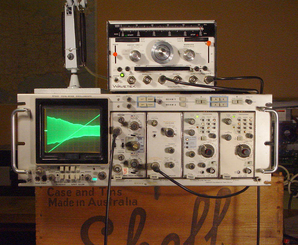
R7704 rackmount 4 slot mainframe, also designed around 1972. ~175MHz.  (Frequency response info is at the end of this page.)

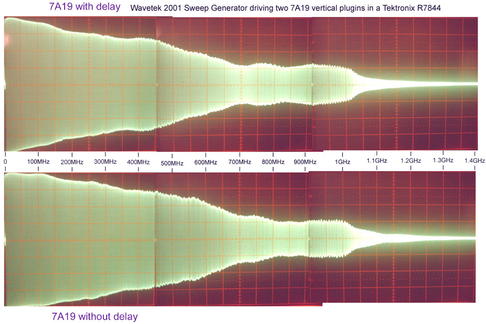
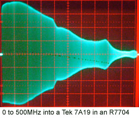
7A19 x 2 vertical plugins. 50 ohm input, response to ~500MHz, depending on the mainframe.  One has a variable delay line.

7A26 x 2 vertical plugins.  1M input, dual input, so a single beam in the R7844 can become a dual trace scope on its own.  With two of these, the machine has four traces.

7B85 delaying timebase.
7B80 delayed timebase.

These can operate independently, or the 7B85 can control when the 7B80 is triggered.  The 7B85 can trigger the 7B80 after a given delay (using a 10 turn pot) or it can enable the 7B80 to trigger itself once from its own trigger source after this delay.  The 7B85 has another 10 turn pot which provides a second brighter spot range on the trace (the delay system produces the first spot or range), for the purpose of measuring elapsed time.  The number is displayed on the lower part of the screen when the digital readout system is turned on.  I have it turned off in the photos below, since its operation detracts from beam 2 - it uses beam 2 intermittently to write the numbers and letters at the top and bottom of the screen.

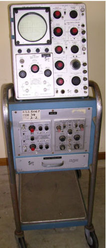
Type 585 valve oscilloscope, designed in 1959.  This is in Adelaide.  We will pick it up later this year.  This has two plugins and a Scope-mobile


The Wavetek 2001 is an RF sweep generator which covers the ~1MHz to 1400MHz spectrum in three overlapping ranges.  There are a few integrated circuits in the powersupply, but the rest of the machine is all transistors. 

The ranges are:

R1  0 (really, a few MHz minimum) to 500MHz.
R2 450MHz to 950MHz.
R3 900MHz to 1400MHz

R1 is produced by heterodyning a higher frequency voltage controlled oscillator with a fixed oscillator.  R2 and R3 are VCOs.  The tuning of all the VCOs is  varactor diodes and fixed inductors.

It can do manually controlled frequencies (CW), via the left horizontal "dial", and the green marker.  This, and a similar dial for the red marker, are 10 turn pots.

It can sweep between the two frequencies set by these dials (S/S).

It can also have a centre frequency set by the green marker and a range set by the red marker using the top scale (delta F).


The orange plastic cylindrical knobs on the switches at either side are my own addition - they are C&K buttons.  The originals were missing.

I bought the operation and service manual from http://www.artekmedia.com .

The ALC input enables the use of an external RF detector, at the input of the device which is being tested.  That can provide a voltage proportional to the RF level at that point, with the Wavetek 2001 adjusting its output in order to achieve a given level at the detector. This is to overcome attenuation and other aspects of non-flat frequency response in the Wavetek 2001 itself, and in the connecting cable.

The Wavetek 2001 normally has one or more crystal-controlled "markers", which generate a spike of voltage when the frequency matches a harmonic of the crystal.  This spike can be used to generate a blip on the vertical and perhaps horizontal (Tilt) signals sent to the scope.  This enables it to be used without a frequency counter, with the blips enabling really accurate adjustment of the sweep range while looking at the display on the scope.  However, this unit has none, and may never have had any.  The calibration procedure relies on these, so I had to calibrate the frequencies of the three ranges in a different manner, using an external frequency counter.

It can also accept a frequency modulation input.  Connections at the back include a signal to lift the pen of a chart recorder.  The sweep can be plenty slow enough to drive a pen plotter.


The design seems to be from the 1970s.  It is very heavy.  I guess they were hand-built, rather than being the product of a slick mass-production plant.  The holes in the module cases for the trimpots have scriber lines to guide the pilot holes.  All the RF signals are on the top of the modules.  The bottom connections are for power and control voltages.  It has +/- 18 volt supplies.


Here they are, sitting on a wooden box from the early 20th century which used to hold two tin-plated steel containers, each with a few gallons of "motor spirit", now known as petrol.  Illumination is by two Studio K Planet Lamps.

The scope has a fine black fabric screen over the CRT.  This is a contrast filter, to reduce the amount of reflected light from the screen, and its plastic protective cover, though it also reduces the amount of light which is visible from the screen.

The scope is displaying the horizontal out of the Wavetek on Beam 1.  I am synchronising the 7B80 (in slot 4) to this, rather than using it to drive the horizontal deflection directly.

Beam 2's horizontal deflection is also from the 7B80.  Beam 2 is displaying the RF signal from the Wavetek, via a 2 metre RG-58C/U cable.  This is showing the Range 2: 450 to 950MHz.

Here is a paste-together of some hand-held photos of the three ranges, for my two 7A19 plugins.


The 7B85 and 7B80 both go to 10ns/cm, with the x10 switch expanding this out to 1ns/cm.

The fastest sinewave I can get the 7B85 to trigger from is about 770MHz, using internal triggering from the 7A19.  The 7B80's limit is around 600MHz - above this, the triggering is erratic.

It would be interesting to see the frequency response with a 1GHz 7A29 vertical plugin, from a 7104, 7103 or R7103.  These are the fastest analogue scopes ever produced.  Their screen is somewhat smaller.  They can apparently produce a single-sweep at their highest speeds, which is visible in ordinary room lighting.

I have never heard of any of these in Australia. One day I would like to get one.  There are plenty of 7104s on eBay, but the costs and risks of shipping a unit like this to Australia have so far dissuaded me from bidding.

I understand that John Bau http://www.users.qwest.net/~jbau/tstequip.htm can supply fully tested R7103s with appropriate modules: 2 x 7A29 and a 7B10 timebase.  I would be tempted to purchase one from him, rather than deal with eBay sellers who can't test the gear and probably have no idea how to pack such large items of equipment.

On 2011-09-07, after a discussion on the Tekscopes list, I wrote this about the bandwidths of the 7A19 and 7A29 in the 7844:

The Barrytech page: http://www.barrytech.com/tektronix/tek7000/tek7a19.html lists the 7A19 as "500MHz", but mentions "600MHz" in the 7100 series, and "400MHz" in the 7800 series.  The 7A19 manual: http://bama.edebris.com/download/tek/7a19/tek-7a19.pdf mentions 500MHz with the 7900 series, and doesn't mention the 7100 series, which was not developed then.

The 7A29 manual: http://bama.edebris.com/download/tek/7a29/tek-7a29.pdf mentions 400MHz for the 7800 series.

The 7844 manual: http://bama.edebris.com/manuals/tek/7844/ (which I did not consult before writing to the list), Table 1-2, mentions for both the 7A19 and the 7A29:

  400MHz bandwidth
  0.9ns  risetime

but that is with P6056 and P6057 probes for the 7A29.  These:  http://www.barrytech.com/tektronix/probes/tekprobes.html are passive probes with bandwidths of 3.5GHz (divide by 10 = 500 ohms) and 1.7GHz (divide by 100 = 5k ohms) respectively.

So there's no reason to believe that a 7A29 will significantly soup up the R7844's frequency response.


On 23 September 2011, I did the same test, to 500MHz, with one of the 7A29 modules in the other Tek scope we have: an R7704.  This is a circa-175MHz mainframe.  The PCBs are copyright 1968 to 1970.  Date codes on components in our machine indicate it was made about 1980.

Frequency response of a Tektronix 7A19 vertical plugin in an R7704 mainframe

The trace can be very bright indeed.  Too bright at times - the scope had this diagonal dotted line of screen-burn when we bought it.

This scope has a 120ns delay line before the final vertical amplifier (Fig 3-36, page 3-33 of the manual).  With a 7B80 timebase, I was able to see at least 70ns of signal before the trigger point.


Search engine bait:  Tektronix 7844  Tektronix 7704.