robin-1 Some very rough ideas for a small blimp
4 March 2002
The following only makes whatever sense it does in the context of the parent directory and the discussion on the Small Blimps mailing list.
I did these sketches late at night. But proper engineering for real flying machines requires a lot of sleep and clear vision.
Scope - Overall mechanical structure, prop, horizontal and vertical steering
Not shown here is how the keel is attached to the envelope. Maybe there
are two helium filled envelopes together in one outer net or blimp-shaped
envelope. That is another department.
The key points proposed here are:
- Two hollow, tapered carbon fibre windsurfer masts are joined at a central
block of something (lets say fabricated aluminium or titanium) to form a
"keel" which attaches to the envelope at many points, via kevlar ropes etc.
Perhaps there are elastic cords in this, so the envelope can expand,
and so that at no point can there bee excessive force which would over-stress
any one attachment point to the envelope. The two spars should flex
nicely (as windsurfer masts are supposed to) and so follow the curve of the
bottom edge of the envelope. There are some potential problems I have
not resolved or thought about much:
- This single dimensional keel not being rigid against rotation left
to right. Only the pilot-seat frame hanging downwards keeps itself
vertical.
- Similarly, there are questions about keeping the propeller spar vertical when there are sideways forces.
- Possible puncture problems with the end of each spar pressing against
he envelope. (All three can be resolved by making the keel of two sets
of spars, and joining them together by some means at each end.
Carbon fibre windsurfer masts are available in lengths up to
about 5.6 metres, and weigh about 2 kg. Longer masts can probably be
obtained for small sailboats. http://www.canamsailcraft.com/masts.html
. 4.9 metre mast weighs 1.75 kg (3.9 pounds). The envelope is likely
to be longer than two such masts end-to-end, but that's fine, I think, with
appropriate suspension to points forward and aft of the ends of the spars.
- Pilot seat and pedal frame is hinged for forwards-backwards movement.
This could be fabricated of aluminium. The two purposes of this
are to:
- Move pilot weight fore and aft in order to guide the blimp into a dive or a climb.
- Linkage of this to the prop spar, to change its angle to achieve the same effect.
This has obvious advantages! Rather than let the chair
hang by gravity, which would require the frame to bend forwards over the
pilot's head, I propose some kind of spring arrangement pushing the frame
forward. Then movement can be controlled by pulling on a lever, wheel
or whatever to tighten a cable going to the rear keel spar to overcome the
spring tension and move the frame backwards. (In a dual keel approach,
the frame can have a left and a right beam, with the pilot reclining between
them, so this spring idea becomes redundant, since it would be fine to have
the pilot's centre of gravity underneath the hinge point. Still, I
think some kind of spring return to centre would be a good idea.)
This system is bound to have complications. Here are a few I can see.
- Forward thrust at the prop tends to push the pilot seat frame forwards,
which is the opposite of what is desired when climbing. This is especially
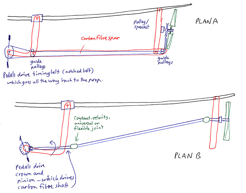
a problem with Plan B (diagram 3), because the full prop force pushes at
the base of the seat frame. In Plan A, only half the prop force acts
on the bottom of the seat frame. An intermediate Plan C is not illustrated
- it has chain or belt drive to a horizontal axis pulley behind the pilot's
seat and half-way up the seat frame. From there, via a CV joint, a
carbon fibre tube takes the drive to the prop, as in Plan B.
- Unless the seat frame angle is rigidly controlled, pilot movement fore and aft will affect prop elevation.
- Likewise any changes in ballast, which makes the positioning of ballast tanks trickier, if they are on the seat frame.
This tilting propeller arrangement is intended to give the
blimp considerable vertical manoeuverability, without the need for any tailplane
or horizontal fins behind the prop. For this to work well, the propeller
should be as close to the rear of the blimp as possible.
It also would have the characteristic of keeping the pilot relatively vertical
to the rest of the world, which is very different from what happens in flying
machines other than ballooons. To the extent that this occurs, then
it would mean the pilot would tend to feel that the envelope is a device
for being pointed upwards and downwards at will, in order that he or she
may move up or down in space. While the angular momentum of the rest
of the craft is likely to be high, and likewise its air-resistance to being
moved, the rest of the craft beyond the pilot, seat-frame and ballast there,
is likely to be lighter than the pilot and seat-frame. To the
extent this is true, then this is not the pilot steering a larger craft,
but the "craft" being a prosthesis - lighter than the pilot, with
the unique function of providing mobility in three dimensions in free air,
with silence, stability, efficiency and freedom even birds might dream of.
- Not illustrated here, but have the propeller spar fixed to a
single vertical rudder directly behind the prop, and make the spar and fin
rotate over a considerable angle for steering. This, combined with
the ability to pedal backwards, should make the blimp quite manoeuverable
vertically and horizontally.
Here are the diagrams:
Diagram 1 Overall plan
Two carbon-fibre windsurfer masts to form a keel above the pilot, who sits on a frame which can hinge forwards and aft.

Diagram 2 Pilot seat frame movement links to prop thrust vertical angle
This shows the in-principle linkage - the next diagram shows two of the three
ways of achieving the linkage and the power transmission from pedals to prop.
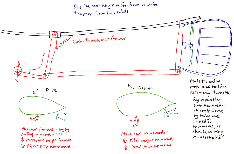
Diagram 3 Two of three ways of linking to the prop
Plan A shows a separation of the prop angle and the prop
rotational linkage. The angle is controlled by a horizontal carbon-fibre
spar (blue) and the rotational linkage is by a belt, such as a toothed timing
belt, which traverses and admittedly tortuous path from the pedals to the
pulley on the prop shaft. Careful attention is needed to the placement
of guide pulleys so belt tension is unaffected by all possible movements.
This approach has some additional challenges with the need to rotate
the prop left - right for steering. Also, the prop will be light and
fairly large, and we don't want it hitting the belts. Maybe put the
pulley forward of the prop spar instead of where I show it here, between the
prop spar and the prop.
Plan B is more BMWish than Jap-bikish! To hell with
the chains and belts! Here, we need two constant velocity joints, because
ordinary universal joints will cause trouble when the prop shaft and the
pinion shaft (under the pilot's seat) are not aligned. They may never
be aligned, and the need to steer the prop left and right means there will
be many times when they are not aligned. We would like quite acute
steering for the prop, but this is a challenge for any CV joint, or other
flexible drive arrangement. CV joints, at least like those found in
the rear axles of Volkswagen vans, are like the opposite of ball bearings
- the inner race will not rotate with respect to the outer, but it can swivel
and slide forwards and backwards. Yet in Plan B, we are relying on
the joints not having any forwards or backwards movement. These are rough
plans of the "barely warming the oven" form, not even half-baked ideas yet.
Plan B is obviously more elegant, since we have the single long carbon
fibre spar doing double duty - torsional drive for rotating the prop and
longitudinal drive to control its vertical angle. But this double duty
means we need the spar to be stronger than otherwise. On the other
hand, in Plan A, the spar there needs to take the full force of the belt
tension with which we are driving the prop - which will be a lot higher than
the force the prop sends back to the pilot chair.
Plan C is a combination of the two, and is not illustrated.
Here, there is a belt and pulley arrangement to drive a horizontal
shaft behind the pilot's seat. about level with the prop shaft. Then
there is a CV joint, and the rest is as per Plan B. The advantage of
this is that the full force of the prop's thrust meets the pilot chair halfway
up, rather than at the bottom, as in Plan B.
I have not attempted to illustrate how the prop and rudder might twist on
a vertical axis for steering. One way to make the link at the top of
the prop spar where it meets the rear keel spar is to join the two with a
small piece of industrial rubber with fabric internal webbing. This
will be simple, strong and give enough flex for steering and tilting the
prop.
Copyright 2002 Robin Whittle, but if you want to use it, let me know. For
the purposes of patent law, this should constitute publication.