Short version:
These are the best or perhaps the only
type of socket which I think does the job properly. This style of socket seems to be made
by several manufacturers. Some of these sockets have a primary
contact which does not work properly - it can become deformed so it no
longer presses against the NC contact.
QingPu Electronics have solved this problem by using a thinner material
for the primary contact, made of beryllium-copper. This works
like a charm.
In 2014, US supplier Erthenvar has this kind of socket from QingPu.
They sell them at attractive prices in lots of 100, which is far more
convenient for many folks than the 5000 MOQ (Minimum Order Quantity) of
QingPu themselves.
Update 2014-05-29: These are available in batches of 50 from Thonk in the UK:
http://www.thonk.co.uk/product-category/diy-accessories/jacks/ .
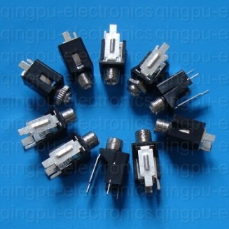
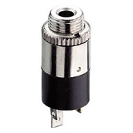
The abovementioned wiki page pointed to this socket:
made by
Wenzhou QingPu Electronics Co. of Wenzhou City, south of
Shanghai. They make a huge range of switches and connectors.
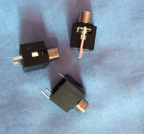
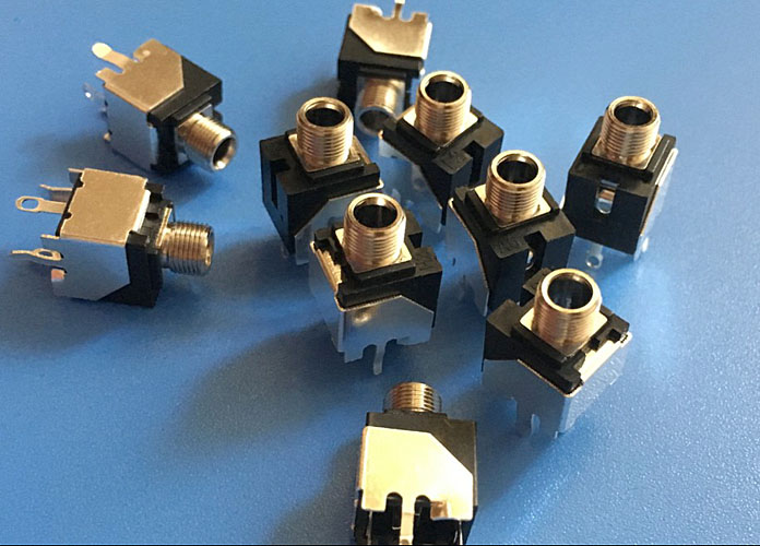
Here are some photos of some QingPu samples sent to me in mid-November 2012:
1.
2.
3.
4.
5.
6.
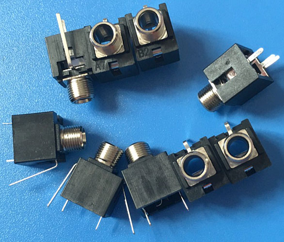
In early November 2012 I purchased some similar sockets from
Erthenvar in the USA:
This was a good deal - 100 sockets (without nuts or washers) for USD$25,
plus postage. This is far better pricing than any for other 3.5mm
sockets I could find at mainstream electronic component suppliers:
Erthenvar sell knurled (round) nuts, hex nuts and washers separately.
When I bought this set of 100 sockets in early November 2012, the
Erthenvar page had a note: "We are currently investigating the
reliability of the jack's switch functionality."
Sure enough, the switch function of these sockets would not work if the
plug was inserted and moved around with force, bending the primary
contact more than would be the case if it was simply inserted in a
gentle manner. The primary contact would become permanently
deformed so it would no longer press against the NC contacts.
Then I began searching for alternatives and found the QingPu Electronics page:
On a Sunday afternoon (in Australia and China) I wrote to the Sales
Manager Edan Wang, via the web-page's contact form, and received a
helpful reply at 7:35 that evening. We exchanged more
emails that night and over the next few days.
He assured me that their new production of these sockets involved a
beryllium-copper primary contact, and that this had no deformation
problems. I guess the primary contact material of the sockets I
bought from Erthenvar was phosphor bronze.
Over the next two weeks I exchanged many emails with Edan. He
always responded helpfully and quickly. Thanks Edan for your help!
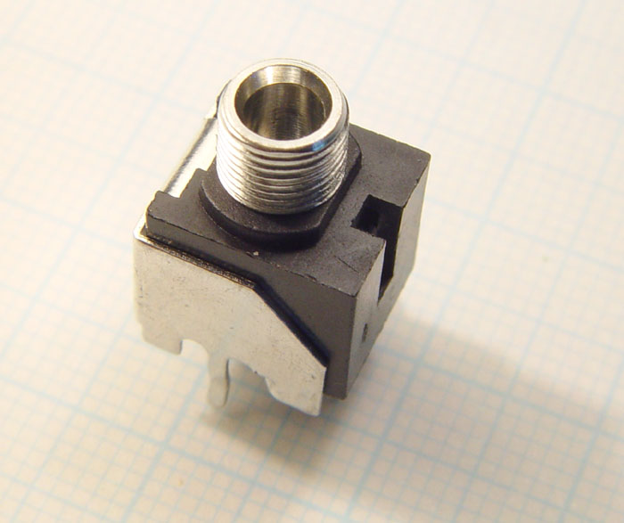
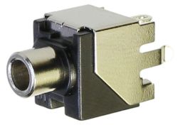
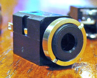
On 27 November I received some samples from QingPu Electronics. One of
the sockets is pictured above and below. There is no problem with
deformation - I tried every reasonable and unreasonable motion with a
plug in the socket and the primary contact always returned properly to
the NC contacts.
The first set of sockets I bought - the ones where the primary contact
would deform - had their primary contacts made from 0.250mm thick metal,
including plating. The new sockets with the beryllium-copper
primary contacts used 0.205mm thick metal. Both springs were strong,
but the thinner beryllium-copper one could be bent much further without
deformation.
In both types of socket, the NC contact was made of 0.250mm metal.
These sockets are the best ones I know of. Edan quoted me an
MOQ of
5000 pieces at USD$0.135 - without nuts. This was
late November 2012. Many factors determine pricing so please ask
for
a quote rather than assume this is the price in the future. Edan told
me that freight to the US was about USD$175, so I guess the total cost
with my choice of nuts and washers would be about USD$900 for 5000
pieces, which is more than
I will need in the foreseeable future. Edan told me that an order
of the new
beryllium-copper model of these sockets had just been shipped to the
Erthenvar people, so by early December 2012 I should be able to get the
quantities I need from
Erthenvar, without great expense.
The socket in greater detail
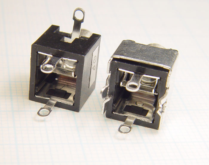
The WQP-PJ3010BM has much in common with this kind of non-PCB-mount, 3.5mm socket:
which is pictured in images 7 and 8 below. Edan sent me some
samples of these too, which also had the non-deformable
beryllium-copper primary contacts.
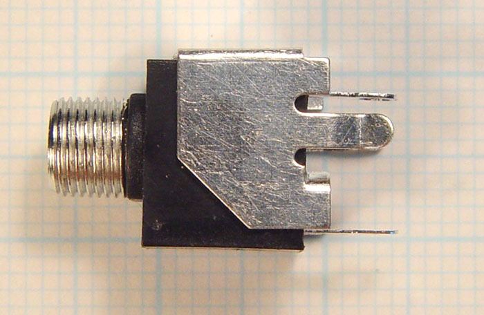
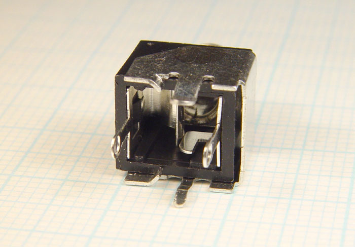
The difference is that the WQP-PJ3010BM has an elaborate metal piece
for the ground contact, which wraps around three sides of the plastic
body and has two strong ground terminals which are ideal for PCB
mounting. This provides a generally robust PCB mounting, but
there are some problems.
Firstly, the ground piece is not bent exactly at right-angles from its
internal peened-over connection with the threaded bush. This
means that when soldered flush with the PCB, the central axis of the
bush will not be at right-angles to the PCB. I haven't measured
this precisely, but in the first photo above you can see the bush
pointing up a little, with the base of the ground piece aligned closely
with the graph paper.
This would be a consideration in several ways:
- If the front panel had multiple sockets like this, it would be
best to orient them in one way, so that the error in the bushing
position was all the same magnitude and direction.
- If the bushings were mounted closely in front panel holes, the entire PCB might be offset a fraction of a mm.
However,
once the nut is tightened, this would tend to straighten up the
socket's body, so the final angle and positioning error would probably
be greatly reduced.
A potential solution might be to use the primary contact terminal
(lower pin on the first photo, right pin of the last photo above) to
pull that part of the plastic body of the socket closer to the PCB top
surface. However, I think this may fail due to all the tension
being taken by a small piece of plastic which clips into the primary
contact. During soldering, I think it is possible that this
plastic would be softened by heat flowing through the primary contact.
See below for a better technique for fixing this "not-quite-90-degrees"
problem - bending the two larger of the four feet out a little, to
reduce their height, and so to correct for the ground piece being not
quite on axis with thebody and bush of the socket.
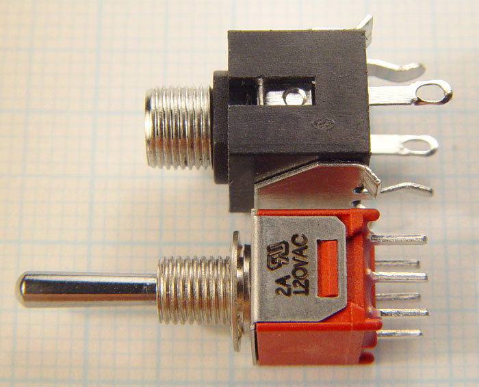
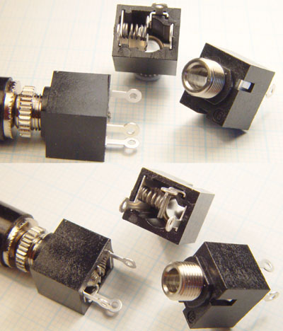
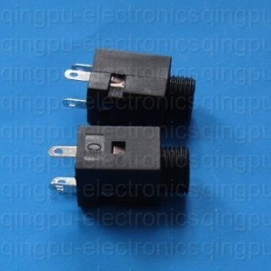
Here are two photos of the WQP-PJ3010BM together with the more
conventional, non-PCB-mount, WQP-PJ301M style of socket which I think
it is based on.
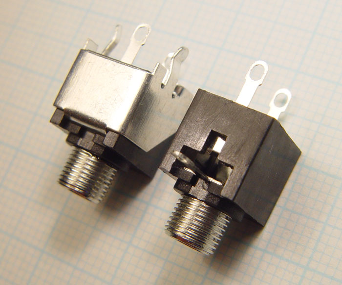
7.
8.
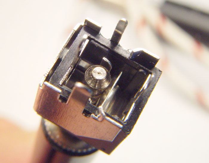
In image 8, the plastic clip which holds in the
primary contact can be seen - a wedge-shaped part of the case inside a
rectangular hole in the primary contact. The two sockets have
different pressings for their primary contacts. The
WQP-PJ3010BM's primary contact has a small circular depression in
it. I am not sure what this is for.
In image 8 a gap can be seen between the metal ground
piece and the side of the plastic body, near the top of the
WQP-PJ3010BM on the right. This is due to the bend from the ground piece
which is fixed onto the bushing, inside the socket, not being quite 90
degrees. It is tempting to think this could be corrected by
graunching it with some pliers, ViseGrips or similar. However,
this could only be achieved by pushing the two little diagonal tabs
on either side into the plastic body, or by allowing those side pieces
to spread outwards.
See below for a technique of correcting for this "not-quite-90-degrees" problem.
One notable and welcome feature is that there are two contacts for the
NC function. This is bound to be more reliable than just one
contact. Contacts such as these which are simply pressed against
each other are subject to a problem know as "fretting corrosion".
There's no easy fix for it, but
having two contacts in parallel will be more reliable, since it would be less likely for both contacts to have fretting corrosion at the same time than just one.
Sidebar on "fretting corrosion":
I first encountered this term when
searching for an explanation of why the NC contact in some other 3.5mm
sockets (like these:
PJ302M-57.html) occasionally went OC (open circuit) even when the contact was
pressing normally on it. This occurred in some Devil Fishes in the
CV-In socket, the only one of its 3.5mm sockets which used the NC contact. The fix was to insert and remove a plug a
dozen or two times, especially while rotating the plug to cause the
contact surfaces to slide somewhat while opening and closing, rather
than just pressing in exactly the same location. After this discovery, I modified
the sockets in all new Devil Fishes to provide greater contact force. I think this reduced
the problem, but it was highly intermittent and so it is difficult to
be certain about its occurrence.
A 1974 paper "Fretting Corrosion in Electrical Contacts" may be of interest:
Although the WQP-PJ3010BM is ostensibly a PCB-mount socket, its primary
contact and NC contact terminals are solder-lugs, not PCB pins I
think this is due to the history of this design, being derived from a
solder-lug socket as shown in images 7 and 8 above.
The wider part of the solder lug terminals is a little over 3.0mm
wide. If a 3.0mm hole was used, the thinner part of the terminal,
which actually transits the hole, would be a loose fit, since it is
only about 2.0mm wide, so there would be a large volume of solder in
the hole, with considerable gap between the hole and the
terminal. I think the best option would be to
squeeze the lug part in pliers to make it 2.0mm as well. With
care, this can be done quickly and without twisting the whole
terminal. (See image 10 below.)
The two ground terminals will be fine for PCB mounting. One is about 1.0mm wide and the other is 2.5mm.
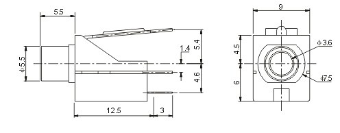
I found that the drawings provided with 3.5mm sockets were not always
accurate. Here are my measurements of the most important aspects
of the WQP-PJ3010BM:
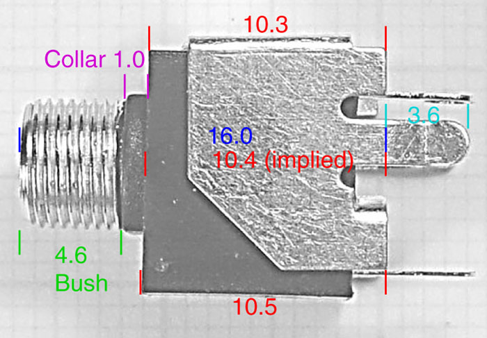
9.
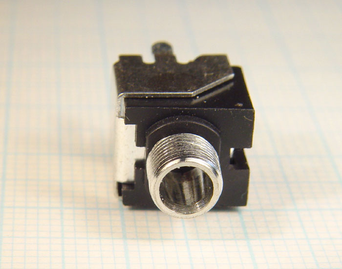
The collar does not extend much above or below the 6.0mm threaded bush,
but it does extend to either side, as can be seen in some images above
and below. The diameter of the collar is 7.7mm, so we would need
about a 7.8 to 7.9mm hole in the front panel to clear it. This
would typically be a round hole, drilled. However it could be a
laser-cut or punched hole in the truncated-circular shape of collar.
Not shown in image 9 is the distance from the four feet (two are
visible at the upper right and lower right) and the base of the plastic
case. This is about 1.3 to 1.5mm. It is possible, as I
illustrate below, to bend these out in order to reduce the total height
of most of the socket above the PCB. This bending is also a means
of
correcting for the not-quite-90-degrees problem.
With a few second's work with a pair of pointy-nose pliers it is
possible to flatten the two larger feet (lower right in the above
image) and to bend them out. Bending them out just a little
corrects for the not-quite-90-degree problem. This will take up
more PCB space, but that is unlikely to be a problem, since we can't
mount other sockets like this or most other connectors right next to
the socket.
The round knurled nuts are 2.0mm thick and 7.9mm diameter.
The hex nuts are 1.5mm thick and 8.0m AF (Across the Flats). The
washers (from Erthenvar - I guess they are either from QingPu or are
the same as those from QingPu) are 1.0mm thick and 10.0mm diameter.
This gives rise to a number of Panel Strategies with differing "Panel
Gaps" - the term I use to refer to the distance between the bottom
(left on the above image) of the front panel and the top (right of the
above image) of the PCB.
Before considering Panel Strategies, there are several Nut
Strategies. I assume that nuts will be used, firstly to ensure
most of the mechanical stress of plug insertion and removal goes
through the front panel and secondly so the front panel's support of
the sockets (I assume several are being used) is part of, or perhaps
the main component of, the mechanical connection between the front
panel and the PCB. "FP" is Front Panel.
Nut Strategy
|
Hole diameter
|
Notes
|
nsA: Knurled nut
(2.0mm)
|
6mm
|
FP presses against top of
collar. The 2mm thickness of the knurled nut enables FP
thicknesses to 2.6mm. However, how do we ensure that the nut
doesn't scratch the front of the FP? Perhaps there is no visible
scratching with these round knurled nuts. However, without a
flat-washer or better still a lock-washer, the nut may be prone to
working loose.
Maybe the FP is covered in most places by a screen-printed-from-behind
polycarbonate faceplate/decal, as in the Devil Fish. If so, it is
best not to have nut pressure on the polycarbonate. So the
polycarbonate label would be punched with a hole to clear the knurled
nut diameter, which is 8.0mm.
I wonder where very fine internal tooth lock-washers could be found for the 5.9mm (actual) diameter threaded bush.
|
nsB: Knurled nut and flat washer
(2.0 + 1.0 or less mm)
|
6mm
|
FP presses against top of collar.
The flat washer is 10mm diameter. It might be best to get some
which are less than 1.0mm thick. If we could get one about 0.6mm
thick, then we could use a 2.0mm FP. This avoids any visible
scratching of the FP.
|
nsC: Hex nut and flat washer
(1.5 + 1.0 or less mm)
|
6mm
|
FP presses against top of collar.
This is more promising, since the hex nut is thinner, even with a 1.0mm
thick flat washer, we can accommodate a 2.0mm thick FP without any
trouble.
|
nsD: Knurled nut and flat washer
(2.0 + 1.0 or less mm)
|
7.8mm
|
Collar goes through FP hole, so FP presses against the top of the main plastic body.
This reduces the Panel Gap by 1.0mm.
Now we have 5.6mm to play with, the 2.6mm taken up by the the nut
and washer is no problem. We can use a FP thicker than 2.0mm
and/or have a lock-washer or split-spring washer behind the FP to help
stabilize the nut.
(We can't have a circular 7.8mm hole without the flat washer, or
perhaps an internal-tooth lockwasher, on top of the FP, because both
the knurled and hex nuts would fall into the hole. Even if the
truncated-circular collar-shaped hole was punched or laser-cut, there
would be too little FP material for the nut to press against.)
|
nsE: Hex nut and flat washer
(1.5 + 1.0 or less mm) |
7.8mm |
As for nsD, but we have an extra 0.5mm for the FP thickness and/or a lock/spring washer.
|
nsF: Just a knurled nut somewhat recessed in a judiciously countersunk hole in the FP.
|
6.0mm
|
This allows still greater FP
thicknesses, or with packing washers between the socket's collar or
body and the bottom of the FP, a greater Panel Gap thanis possible with the above approaches.
|
Here are some
Panel Strategies with Panel Gaps assuming a FP thickness of 2.0mm.
Panel Strategy and Nut Strategy
|
Panel Gap
|
Notes
|
psA with nsA, nsB, or nsC (all 6.0mm holes)
|
11.4mm
|
The socket mounts conventionally on the PCB and the FP presses against the collar.
|
psB with nsF (6.0mm holes)
|
Somewhat greater than 11.4mm, say 12.0mm.
|
The socket mounts
conventionally on the PCB and the FP is some small distance from the
collar, with one or more flat washers, split-spring washers or
internal/external lock-washers between the bottom of the FP and the top
of the collar. |
psC with nsD or nsE (7.8mm holes)
|
10.4mm
|
The socket mounts
conventionally on the PCB and the FP presses against the body of the
socket, with the collar going through the FP hole. |
| psD with nsD or nsE (7.8mm holes) |
10.4mm to as little as 9.0mm
|
Bend the four feet out to
some degree (see photo 10), or as far as bending them at right-angles
so they do not lift the socket's body off the PCB at all. For the
lowest Panel Gap, it may be possible to cut these feet off rather then
bend them out, but I think bending them out would be easier.
With this strategy, it may suffice to cut the Primary and NC Contact
terminals short rather than squeeze the lug part to be 2.0mm wide,
since the whole socket is now closer to the PCB and we may not need the
lug part of these terminals. However, see below about stresses on
the Primary Contact terminal.
When the plastic body is flush against the PCB, with the four feet bent
out of the way at right-angles, the tip of the plug may touch the
PCB. Normally there is 16.0mm between the entrance of the bushing
and the top of the PCB, but with the four feet bend out of the way,
this is reduced to about 14.6mm. As far as I know, there's no
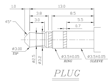
technical standard for the length 3.5mm plugs. (From the PDF for
the Lih Sheng LJE0352 mentioned below, here is a drawing of a stereo
plug, with the length specifed as 14.0mm: 3.5mm-stereo-plug-dimensions-from-Lih-Sheng-Precision-Industrial.png .) Are any longer
than 14.6mm? . . . quick measurements of plugs around the workshop
found lengths between 14.1 and 14.8mm. It probably doesn't matter
if the plug is stopped by the front panel from going the last 0.2mm or
similar fully into the socket, but we need to ensure that there are no
copper tracks in that vicinity. A hole or countersunk area might
be better than the plug hittingthe PCB.
|
psE
|
12.0 to 14.0mm?
|
If there was some way of
mounting the socket with its four feet 0.1 to 2.0mm above the PCB, this
would increase the above Panel Gaps by this amount.
|
So it looks like we can use these sockets with 2.0mm thick front panels
to get Panel Gaps between about 9.0mm and 12.0mm - or has much as 13 or
14mm with some as-yet unknown method of soldering the socket somewhat
above its normal flush with the PCB location.
I want to use C&K Tiny Toggle switches, such as the T101, T201 and
T211. The minimum Panel Gap for these is about 8.8mm. Their
threaded bush length is 5.6mm, so with a lockwasher between the FP and
the switch, I still have plenty of bush length for the FP and a
lock-washer and nut on top. A single internal-star lock-washer
from C&K is 0.6mm when compressed. With that between the FP
and the switch, I would have a Panel Gap of 9.4mm. This can be
achieved with a few seconds bending of the four feet. That is
enough beyond 9.0mm to have no concern about the tip of the plug
hitting the PCB. So this looks most promising:
10.
Stresses on the Primary Contact terminal
One potential problem with these sockets is that the Primary Contact is
subject to considerable forces as the plug is inserted and
removed. This terminal is not firmly anchored in the socket body
- it can move up and down a little (left and right in the image 9
above). With a conventional solder-joint, this means the Primary
Contact terminal may be placing considerable stresses on this
solder-joint. Especially with lead-free solder, I am concerned
about this joint fracturing.
(I have been fixing electronic things since the late 60s and I am very
wary of metal fatigue in solder joints. I want to manufacture
gear which will be used for decades without such problems.)
However, the path for the force is not direct. At the right of photo 8
above it can be seen that the Primary Contact's base has a rectangular
hole in it, with the idea that at least some of the force from plugging
a plug into the socket be taken by the wedge-shaped plastic part of the
case which holds it in place.
One solution might be to place the terminal through a hole in which it
is not soldered and then bend it 90 degrees over to another hole to
which it is soldered. However that would involve flexing of the
terminal and changing forces where it meets its solder joints.
Probably the best approach is to use a solid solder joint with a hole
which is a close fit for the terminal. A non-circular hole would
be better still, but this may not always be achievable, depending on
the PCB manufacturing process. I will think more about this.
Musical instruments can get a hammering, for decades. While a
broken solder joint is easy for a technician to fix - compared to
something like a failed SMD microcontroller - it would still be best if
the fault never occurred in the first place.
