![]()
Modifications for the TR-909
New sound controls; external inputs for
SD and HCP; pot cleaning, firmware (EPROM) update and other maintenance
items.
© Robin Whittle, Real World Interfaces, Daylesford, Victoria, Australia rw@firstpr.com.au 27 February 2020
(2020-02-27) I have a backlog of Devil Fish work, in part because I have been prioritising TR-808 work. For the first half of 2020 and perhaps longer I will be prioritising Devil Fish work on TB-303s and TT-303 Bass Bots, so it may be some time before I accept more TR-606, TR-808 or TR-909 work.
prices-au/ Prices
for Australian customers.
prices-int/ Prices
for customers outside Australia.
To the
Devil
Fish page for TB-303 modifications.
To the TR-808 modification page: ../tr-808/ .
To the TR-606 modification page: ../tr-606/ .
To the Real World Interfaces page. To to the main First Principles site.
TR-909s are extremely valuable - too valuable to send via Australia Post. Please see: ../freight-insurance
>>> General repairs, pot
cleaning and firmware update
>>>
Sound
modifications
If you can't find anyone else to work on your TR-909, I can do repair work and pot cleaning. However, please see the link above regarding freight and insurance, particularly if you are considering sending the machine from overseas.
The TR-909 is difficult to work on, since the component sides of the two main circuit boards are normally not accessible when they are connected inside the machine. I have extension cables to enable me to access both sides of the PCBs when they are connected and operating.
I have only occasionally worked on TR-909s since they came out. As far as I know all the push-button switches are quite reliable. The small tact switches (with and without LEDs) can be dismantled and cleaned, which is quite remarkable. I have not encountered any failure of the switches of the 16 main buttons and one Function button.
The LEDs inside the buttons can be rather dim and uneven, but it would be a lot of work to replace them. Its not out of the question that I could do this if someone really wanted them to be more consistently brighter.
#npn
In two machines I worked on in early 2018, three NPN transistors (2SC2603-F) were faulty, producing two faults in one machine and one fault in the other. These machines were made a year or more apart, so I think this whole set of 2SC2603-F transistors may be unreliable, rather than just one specific batch. Steve Jones (https://secretlifeofsynthesizers.com) has confirmed this: There are about 61 of these transistors in each TR-909. It would be a lot of work to replace them all. 3 failures over 122 transistors which are all about 35 years old is higher than the general failure rate for electronic components. I still think it indicates that other TR-909s may have the same kind of trouble as the decades parade past our eyes.
#firmware
It is important to upgrade the firmware to version 4.0. This solves a problem with the machine not recognising the first MIDI In Clock byte following the Start byte, if this Clock byte follows by less than 1ms. For many sources of MIDI Sync, it would be the very next byte, which arrives 0.3ms after the Start byte.
To find which version of the firmware your machine has, turn it on with the Track 1 button pressed. One of the 16 button LEDs 1 to 4 will light up. The service manual only mentions versions 1 and 2.
You can buy pre-programed EPROMs with this firmware from:
The above page has a copy of the note from Roland describing the problem:
TR-909 will rarely miss-read a $F8 (MIDI Clock) just after
Start data.
REASON
The interval between Start data and the first Clock of the
MPU-401 is so short (about 1msec).
Due to space constraints the EPROM (28 pin 27C64, 250nsec or less access time) is soldered to the front panel CPU board. The above seller provides a socket so the new EPROM can be in the socket, in case it ever needs to be removed. However, I can't see how any EPROM could fit with any socket I know of, given the clearance of 8.2mm.
I solder the new EPROM to the PCB, rather than use a socket. I do so in a way that the EPROM is raised 1.5mm or so, in order that only the thin parts of the pins are in the holes, so it will be easier to desolder if this is ever necessary. (Normally the thick parts of the pins would be resting on the tops of the holes, which makes desoldering mare difficult are more likely to damage the PCB.)
I use a 27C256, with the firmware programmed into the 4000 to 5FFF locations, because 27C256s are more modern, faster and easier to obtain than 27C64s. This requires that pin 26 be grounded. That said, in 2018, no conventional supplier such as element14, RS Components, Mouser or Digikey supplies 27C256s, since they went out of production around the turn of century. Furthermore, the great majority of 27C256 EPROMs for sale on eBay are fakes, in that they are modern chips made by some unknown company and falsely marked as being ST or some other brand. I use EPROMs which I have had since the 1980s or which I have purchased more recently and whose the chip, package and markings exactly resemble the original devices I have had from those days.
Here is a zip file of the firmware in raw binary form, with a second file ready to be programmed into a 27C256 as just described: TR-909-firmware-V4.zip .
Version 4 is missing one feature: the ability to load the "factory patterns" into RAM, otherwise known as "clearing memory". With version 1 (the only other firmware version I have tested so far) this is achieved by turning the machine on with Track 1 and Pattern 1 buttons pressed. (See page 7 of the service manual for full details.) Therefore to clear all the patterns and to delete any chaining of multiple patterns together, it is necessary to use these steps on each pattern, perhaps by running through them all 1 to 16 and 16 to 1. Both these require that the machine be in Pattern Write mode: Hold the Shift key down and press one of the three Pattern buttons, which will cause the LED in that button to flash.
To unchain (unlink) a pattern, hold down the key 1 to 16 for that pattern and then press and release the Enter key.
To clear a pattern, hold down the Clear button and press and release the key 1 to 16 for that pattern.
Here is the PDF file which describes the above, as I include in the comb-bound manual with the Sound Modification details: TR-909-Firmware.pdf .
(Search engine bait: TR-909 clear memory initialize RAM load default patterns.)
#ramchip
The patterns and tracks are stored in a TC-5565P-15 static RAM chip. (150ns access time.) Its pin-out is the same as a standard 6264 static RAM, and - as far as I can tell - the same as Toshiba's TC-5564P RAM chips. (I am not sure what the difference is between these two types of Toshiba chip.) If the RAM chip is faulty, it can be replaced with any 6264-style 8k x 8 RAM chip, but it is important to use one which has a standby current of 1uA or so. The current will change with temperature, and the actual currents of these chips are far below the maximum current specified in the data sheet, which might be hundreds of times more than this. You can't just rely on data sheets to select a chip, since none of them show currents as low as the chips in practice actually have.
I have replaced these chips with NEC D4364C-15L chips. The LL series are specified to have lower maximum standby currents than the L series, so either L or LL would be fine.
The RAM chip's battery backup circuit is simple: a ~3V battery voltage goes via a diode to a 10uF capacitor (C6) which supplies the RAM chip. I replace C6 with a 1000uF capacitor, so the memory contents are likely to remain unaffected when changing the battery with the power disconnected, as long as the new batteries are installed within 5 minutes. The other change is to install a 0.22uF monolithic ceramic capacitor directly across pins 14 and 28 of the RAM chip, since in the original circuit the only bypass capacitor is C6 via a 20cm track. I make these changes to all TR-909s I work on. Normally there is no need to replace the RAM chip itself.
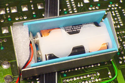
#batteries
When the machine is turned off, the data in this memory chip is retained by about 3 volts (via a diode, so about 2.5 volts to the RAM chip) supplied by two AA cells in the battery compartment. These should be alkaline batteries, which have longer lives and are less likely to leak than ordinary carbon-zinc batteries.
I can also install a cylindrical CR1/2AA non-rechargeable lithium battery in a holder, within the battery compartment. These have a very low self-discharge rate, and so will probably work for many decades. As far as I know, they do not leak even when fully discharged. Here is the documentation for this modification:
With the original double AA arrangement, please use Duracell or Energizer alkaline batteries. When fresh these are typically specified as having a 10 year shelf life. The current drain of the memory chip - such as 0.000002 amps - is very small compared to the capacity of the batteries themselves, not counting self-discharge, which is about 2.4 amp hours. Without self-discharge, the batteries would last for 137 years. I suggest installing fresh alkaline batteries every 5 years, with the machine turned on while you change them.
These batteries fit into a special holder which has terminals like a 9 volt battery, and this clips into a conventional 9 volt battery snap. The trouble is that if the battery holder goes missing, then one might be tempted to plug in a 9 volt battery. If a 9 volt battery has been attached, the RAM chip should be replaced, since it can't be ruled out that the 8 volts or so might damage the chip in some subtle way which could cause erratic operation.
It is tricky to find these 2 x AA battery holders with the 9V battery style clips. In April 2018 I bought some from this eBay seller in Adelaide StampsaPlus. Here is the final battery compartment arrangement with EVA and polyethylene foam to secure battery holder. Another piece of polyethylene foam goes on top of the battery holder.
#updates
There are a series of updates which need to be done to TR-909s with serial numbers below 426700. From the service manual:
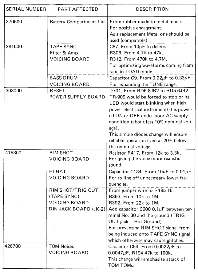
I will usually do all these updates apart from the first, which involves replacing a rubber battery compartment cover with a metal one. If the cover is missing, I will be able to create one from aluminium, but it won't be as attractive as the stainless steel ones made by Roland.
For overseas customers, the cost of insured shipping in both directions, plus the cost of getting the package through Australian Customs (typically AUD$100) is significant, so I suggest finding a technician closer to home for this work, unless you also want the sound modifications - in which case it is best if I do all the repair work.
Whenever I work on a TR-909, I clean the the case, buttons and knobs, test the machine and do any necessary repairs.
The Volume pot is typically noisy. Whether or not it is noisy, I dismantle and clean it with isopropyl alcohol. This should keep it noise-free for quite a few years.
Without removing them from the circuit boards, I clean the 27 other pots with isopropyl alcohol and compressed air. After a few decades they can become noisy, but this cleaning usually fixes any such problems and will hopefully have them working properly for another decade or two. However, it may be necessary to remove them and dismantle them, which is a lot more work. For instance if someone has sprayed oily contact cleaner on the pots, the whole board will be covered in oil. Theoretically the oil should not cause any problems, but it is best to remove as much of it as possible.
The exact amount of work involved in this or any further repairs can't be determined beforehand. It is best to allow 4 hours for cleaning, including the pots, testing etc. or 8 if the 27 pots need to be dismantled. This includes doing the Roland updates listed above and installing two new capacitors in the memory battery supply circuit, as mentioned above.
I don't normally test the tape sync / data save circuitry, but I can if required. I will only be able to test the cartridge slot if you supply a suitable memory cartridge.
If you want your TR-909 to run from a different mains voltage, there is no need to install a new transformer. You can have a technician alter the internal wiring so it runs from the 100V, 117V, 220V or 240V tap of the primary winding.
The TR-909 operation manual is:
A good copy of the TR-909 service manual (TR-909 schematics) can be found at:
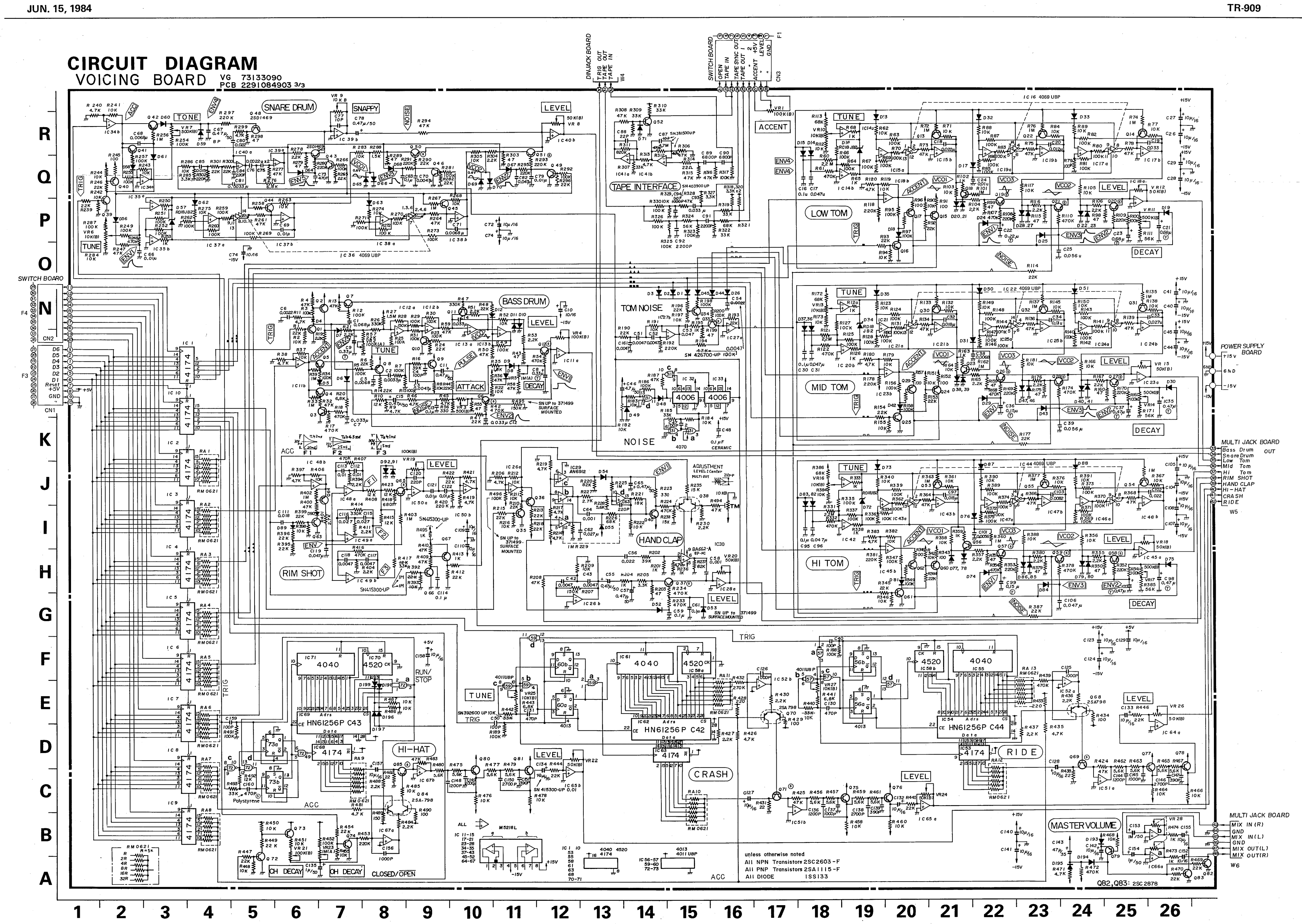
Here is the BD section of the voicing board schematic:
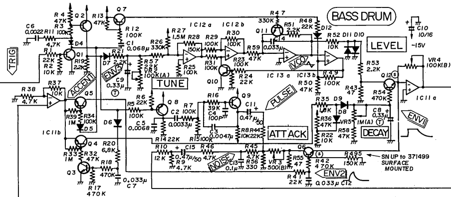
The schematic of the voicing board is about 20 times as complex as this. Here it is as a 3591 x 2550 image: TR-909-schematic-voicing-board.png .
Some TR-909 parts can be obtained from:
This US eBay seller has (April 2018) replica knobs for the TR-909:
Sound modifications
These mods affect the:
For a full description, please see the manual:
- Bass Drum: new controls based on Colin Fraser's mods .
- HiHat: a new pot for tuning, as also first developed by Colin Fraser.
- Snare: A gutsier (more lower mid-range) Snappy signal with a decay closer than usual to exponential, with a range of envelope times (Tone pot) which extends to both shorter and longer than usual.
The lower range of the Tune pot is extended so that it includes zero frequency (no tone) for most of the note, with a short pulse of low frequency at the start.
There is also an external signal input for the Snappy part of the sound, which replaces the white noise signal from the TR-909's internal noise circuit.
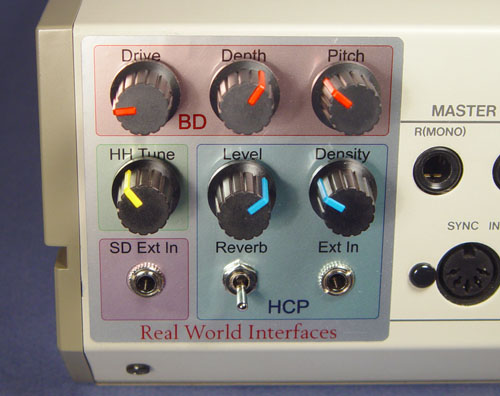
- Hand Clap circuits: A switch to disable the pseudo-reverb component; a pot for Density, a pot for noise Intensity. Also, an external signal input for both components of the sound, which are normally made from the white noise signal of the internal generator.
All the controls and the two signal inputs are mounted at the right rear of the machine, where the cartridge slot used to be:
#soundmoddemo
A SoundCloud demo of the modifications is at:
The demo files are also here. The losslessly compressed FLAC file (open in Audacity) and probably the MP3 file will have higher sound quality than what you hear on SoundCloud:
sounds/TR-909-Sound-Mods-Real-World-Interfaces.flac 107MB
sounds/TR-909-Sound-Mods-Real-World-Interfaces-320kbps-stereo.mp3 51MB
0:00 HiHat tuning.
0:46 Bass Drum new controls .
5:40 Snare Drum mods.
10:41 Snare Drum external signal input for the Snappy part - intro.
12:41 Snare Drum external signal input for the Snappy part - sounds.
15:09 Hand Clap new controls.
20:38 Hand Clap external input.
The sound mods manual contains details of the actual modifications, in text form, but not with schematics or PCB layout details. Colin Fraser's instructions linked to above contain PCB details of his mods. Someone with sufficient patience and skill could, therefore, reproduce these mods, but they will need to do a lot of work to understand it all, draw out their own modified schematics etc.
I have given these details partly in the spirit with which Colin made his details available, and also because it is the only way to really describe what the changes entail. The manual is specific about the circuit changes and attempts to describe what these sound like. If anyone tries these mods and finds any errors in what I wrote, or suggestions for improvement, please let me know. I do not provide free support for anyone doing these modifications, and I suggest that they should only be attempted by someone with years of experience with musical instrument electronics who has a great deal of patience.
The switch is a C&K T101 and the pots are made by Taiwan Alpha. It is tricky to get these 9mm spline-shaft pots. I got mine from Jaycar.com.au.
The sockets are "Thonkiconn" which Thonk call PJ301M-12, but which I think are really the improved version of the Qing Pu WQP-PJ398M-12, which has a beryllium-copper spring contact: http://www.qingpu-electronics.com/en/products/WQP-PJ398SM-362.html (See http://www.firstpr.com.au/rwi/parts/3.5mm-sockets/ .)The knobs are the same ones I use on the TR-808. They are Re'an P570 (search for Hard, 2 colors - there is no actual web page, but see: http://www.reanknobs.com/index.php?id=26.) I get them from RapidOnline in the UK: https://www.rapidonline.com/catalogue/search?Query=P570.
The label is made by inkjet printing on a particular material, thoroughly drying it with hot air or in an electric frypan at ~130C and then laminating it with a conventional office laminator. I use an Epson Stylus Pro 3800, but any Epson printer with UltraChrome (pigment) ink should work. The remarkable Japanese self-adhesive material is A-One 29283. I used https://www.fromjapan.co.jp/en/ to get some from a Japanese supplier, but it is now available via Amazon.