
Replacing or repairing TR-808 switches and pots - and a technique
for inkjet printing on satin-silver self-adhesive label material which
can be laminated
2019-03-21 Robin Whittle
rw@firstpr.com.au "Death and taxes are unsolved engineering problems" - Romana Machado.
This page concerns some engineering problems, most of which have now been solved.
Introduction
This page discusses the repair or
replacement of all the TR-808's
switches and pots, with a final detailed section on the Run/Stop
/ Tap
keyswitch. There was an unsolved engineering problem regarding
these switches. They fail and are not easily replaced or
repaired. However, there is a promising replacement kit from Social Entropy: http://socialentropy.com
, and now replacement buttons and covers from "hotairparts" in Vienna,
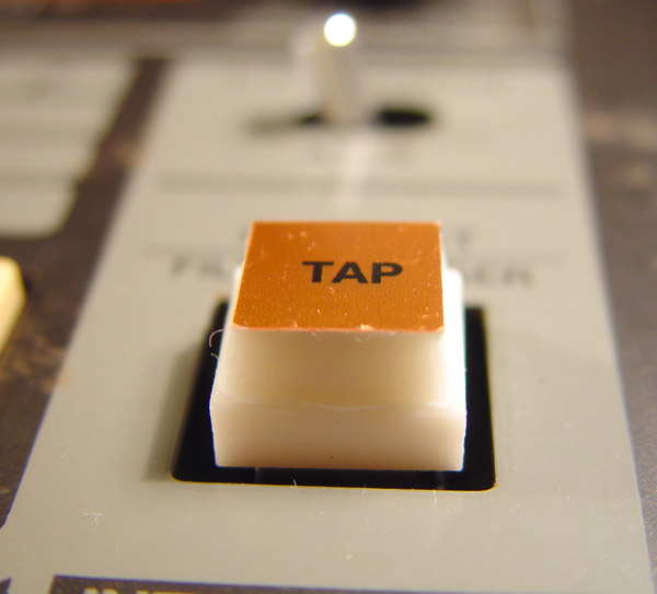
as well as a design for new labels. This section (on Run/Stop and
Tap buttons) includes a description of my inkjet printed matte
aluminium background laminated labeling system (#labelprinting below), which is suitable for front panel prototyping and various other uses.
You may also be interested in my analysis of tact switches for the TB-303:
You may also be interested in my analysis of tact switches for the TB-303:
An update history is at the end: #updates .
The TR-808 Service Manual can be obtained from:
The TR-808 is a mains-operated device with exposed mains connections on the power switch and the power supply board. Working on this machine while it is plugged into a mains socket constitutes a serious safety hazard. To so so risks serious injury and DEATH. If you are not an experienced electronic technician who already knows about mains safety and about static electricity damage to semiconductor devices, I suggest you not dismantle this machine at all.
The TR-808 is a mains-operated device with exposed mains connections on the power switch and the power supply board. Working on this machine while it is plugged into a mains socket constitutes a serious safety hazard. To so so risks serious injury and DEATH. If you are not an experienced electronic technician who already knows about mains safety and about static electricity damage to semiconductor devices, I suggest you not dismantle this machine at all.
TR-808 pots
#Volume-Pot
The Volume pot may become noisy. My fix for this is to de-solder it, dismantle it by bending tabs, and then to clean the contacts with isopropyl alcohol. I usually spin it around a few times (be sure to do so in the direction where the wipers are dragged, rather than pushed) and use little strips of cardboard soaked in isopropyl alcohol. As far as I know, this fixes the problem for a few years at least.
Technology Transplant (who went out of business ca. 2014, previously at www.technologytransplant.com) sold newly manufactured Volume and Tempo pots. I haven't seen any trouble with Tempo pots, but they too could become erratic and benefit from cleaning with isopropyl alcohol. Likewise the Fine Tempo pot.
Many of their products are available from https://www.soundtoparts.com .
#Small-Pots
I have not seen any serious trouble with the many small pots of the TR-808. However, they can become noisy. I clean these pots in the following manner.
- Squirt in a little isopropyl alcohol (IPA) into all the pots.
- Turn each pot one or two dozen times.
- Blow the IPA out with compressed air
- Repeat steps 1, 2 and 3.
- This inevitably causes isopropyl alcohol to go elsewhere on the PCB, so blow it across the board in a way that it drains off one corner. I usually add some extra IPA to wash the dust-contaminated IPA away .
- Leave the whole machine to dry for an hour or so before turning it on again.
I do this for the small pots, the
slider and rocker switches the Tempo pot and the Fine Tempo pot.
I dismantle the Volume pot and clean it with IPA, including its
metal-to-metal wipers with some very fine abrasive paper.
Never spray anything oily inside electronic equipment. Isopropyl alcohol is the only substance I think should ever be sprayed inside a machine, unless perhaps there is a need to wash away something sticky, which might require Shellite (like petrol) or 50/50 water / IPA for dried bourbon and coke.
Never spray anything oily inside electronic equipment. Isopropyl alcohol is the only substance I think should ever be sprayed inside a machine, unless perhaps there is a need to wash away something sticky, which might require Shellite (like petrol) or 50/50 water / IPA for dried bourbon and coke.
TR-808 switches
The section after this one concerns the
Start/Stop and Tap switches. This section concerns all the others.
I have never seen any problems with the three Rotary switches. It appears that ALPS still make this range of switches:
however, it could be tricky to find a supplier with the exact same type for a one-off order.
There is a little push-button switch for Pattern Clear. They are a horrible-feeling switch, with no clicking action at all. I haven't seen one fail. They are probably easy to replace since switches such as these, with integral buttons, are widely available.
There is a 3 position Basic Variation toggle switch and a 2 position I/F Variation A B switch. Technology Transplant sell a pair of these, newly manufactured:
There is a 3 position slider switch for Pre Scale. In my experience, this type of switch can become erratic due to dust, migrating grease and/or corrosion. My first approach to dealing with this would be to squirt some isopropyl alcohol into the switch and move it back and forth a hundred times or so. It is possible to dismantle them for cleaning, but it is tricky getting them back together, and I am not sure that this would be superior to leaving it in-situ and putting some isopropyl alcohol inside it. Likewise the Sync Input / Output switch on the back panel.
I have never worked on the Power switch. Some old Roland mains-powered guitar processing boxes had a similar switch.
#Tact-Switches
The 16 Tact Switches are a particular concern. Much of what follows would also be relevant to the JP-8 (Jupiter 8) which uses the same switches. If you have whole sets of these failing, such as groups of four, then you may have a problem with the printed ribbon cable connecting to the switch board. This is easily fixed by replacing the ribbon with direct wiring from PCB to PCB.
The TR-808 tact switches are ALPS SKHCABs. These are a stemless version of the SKHCAA type used in the TB-303 and TR-606. These are still produced and are known as SKHCBFA010 for the stemless version (TR-808 and JP-8) and SKHCBEA010 for the TB-303 type with stems. These are both "1.27 newton" switches, which means about 124 grams as a force.
I do not recommend using these ALPS switches as replacements. Nor do I recommend using the ALPS sealed tact switches, since they have what I consider to be a very poor action. Other people find this acceptable or desirable in the TB-303, but I can't imagine how they could be better than the Omron switches discussed below. See ../dfish/tact-switches/ for measurements and discussion.
I recommend using Omron B3W-4000 sealed tact switches to replace the ALPS ones used in the TR-808. These have a similar feel and are sealed against liquids and dust. So I expect them to last for many years.
The Omron page for these is:
http://www.components.omron.com/components/web/webfiles.nsf$FILES/family.html?ID=CNEN-6TJQQR
They are available at Farnell, element14 or whatever they call themselves today: http://www.element14.com . Mouser has them at a better price, but the illustration on their page (2012-03-12) shows another switch. http://www.mouser.com .
One approach was to buy a complete replacement switch panel from Technology Transplant. However, in early 2014, this product is no longer available.
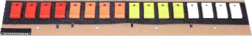
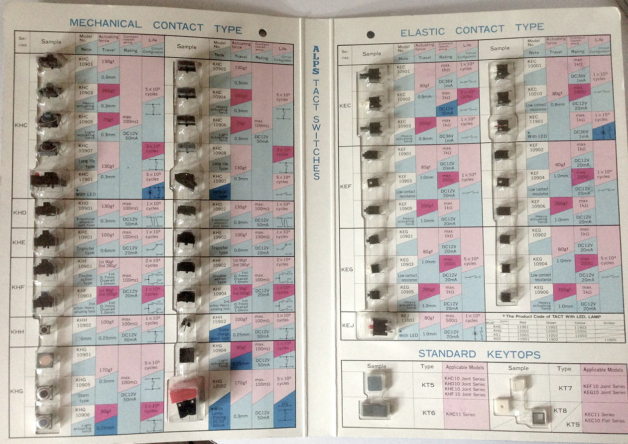
These used newly manufactured actuators (black plastic frame)and buttons. Roland got these black plastic actuators and coloured buttons from ALPS in the early 1980s. John at Social Entropy found an obscure ALPS catalogue page which lists the black actuator, with red LED and tact switch, but without a coloured button, as KHC 11901. Here is the image of the sample-card / catalogue page:
Assuming these are the same as what is used in the TR-808, JP-8 etc, the switch is a 130 grams force "KHC 10902", which must be the older name for what I knew as an SKHCAB, the stem-less version of the SKHCAA (as used in the TB-303) which is now (after ~2009?) known as an SKHCBEA010. ALPS tact switches, such as the SKHCABs used in the TR-808, have four little slots in the underside of the body which seem to be for this style of clip-on actuator.
Searching for "KHC10902" turns up links to service manuals for the Korg Monopoly and PolySix. I recall these use the same tact switch and actuator, but the buttons are a different shape and colour. My hypothesis is that while ALPS supplied the tact switch, actuator and LED, probably as a single component ready to be inserted in the PCB, they did not supply the buttons. Therefore, the Red, Orange, Yellow and White buttons used in the TR-808 (and the JP-8 has Blue) would have been Roland parts.
Technology Transplant had good replicas of the actuators and buttons made for their TR-808 switch board. The new LEDs in their boards were somewhat brighter than the originals, without being excessively bright.
However, the buttons were not absolutely identical in shape or colour, so it wouldn't look quite right to install one of these buttons in place of one which went missing on a TR-808.
A common problem is that a button is missing. This is usually not just the button which has come adrift, but part of the black plastic actuator as well. Therefore, the entire actuator needs to be replaced. The actuator contains a LED and snaps around the switch.
In principle, someone could 3D print new buttons. However, it would be difficult to get the right colour, and I expect there would need to be some manual work smoothing the printed surface to get a nice texture for the part which we touch with our fingers. 3D printing a black actuator would be easy in terms of colour, but really tricky in practice, since it uses a thin piece of plastic as a hinge. This would be really difficult to reproduce in terms of flexibility and longevity, without the original injection molded polypropylene (I guess) plastic.
The Technology Transplant TR-808 switch board was a most welcome development, since it was the only source of replacement actuators and buttons. However, they use the same kind of unsealed tact switches as Roland used - so these switches will fail within a few years, due to dust.
It is possible to significantly prolong the life of these unsealed tact switches by placing a thin strip of Mylar (technically biaxially-oriented polyester/PET) or other plastic between the tops of the switches and the bottom of the flexible part of the actuator. I used Mylar film from 3M "Professional Flip-Frame" overhead Transparency Protectors (RS7110). The strip is a little wider (left-right) than the whole set of buttons and, I recall, about 20mm long (front-back).
However, I believe it is better to use Omron sealed tact switches instead of the new switches in these Technology Transplant switch panels.
Here are some photos of the original ALPS tact switches, the actuators and the buttons.
The actuator has dual thin plastic hinges between the moving part which attaches to the button and the fixed part. This can fatigue with excessive force, or perhaps just lots of use. When this happens, this part of the actuator and the button will come loose and fall off the machine. Please be careful if you remove the button, since the force could break the hinge.
There's no way of repairing this broken actuator, so (sadly, no longer available in 2014) the Technology Transplant replacement boards were highly desirable. However, if someone installs a complete new board, this means they have an old board with at least some good actuators in them. I have one such board and would be interested in acquiring one or two more, so I can use the original actuators and buttons to replace occasional broken actuators on machines I am working on. If you have replaced your original board with a Technology Transport one, and would like to sell me the original board with most of its buttons and actuators, please let me know: rw@firstpr.com.au .
This photo shows that the actuator has four little hooks by which it is aligned with the top surface of the PCB by clipping under the ALPS tact switch, on the left. There are four slots molded into the switch body for this purpose. In August 2012, the machine I worked on had no hooks at the rear of the actuator body. The hooks in the front (lower on the above photo) are minimal. The above photo gives the appearance of hooks at the back, but I am not convinced that these really exist as functional hooks - I suspect they are molding marks. Perhaps the design was changed. There's no strong reason to have hooks at the back, since the actuator is held in place by the LED wires being soldered to the PCB.
The Omron switch on the right has no such slots. Therefore, we need to file away at these four bottom corners of the Omron switch body. In August 2012 I decided that we really only need two slots, on the end of the switch which will be at the front (lower on the following photo). In 2015 I found it better to hold the switch in a vise and cut the plastic with an knife.
The Omron switch bodies are about 0.1mm higher off the PCB (downwards in the above photo) than the ALPS switches. Since we rely on these clips at the front of the switch (bottom of the above photo) to hold the actuator frame flush with the PCB, it is quite tricky filing the right amount of material off the switches. Too little and the clip does not go in at all. Too much and the clip will not hold against the switch body as intended. For doing this faster I used a small milling bit from a Dremel tool, affixed to a drill press, with a guide below. This is tricky, so for a single set of switches I suggest you just use a file. It may help to cut down or file down the two locating lugs in the middle of the switch, so you can get a more shallow angle cut when filing.
Installing Omron sealed tact switches is quite a laborious and tricky task. It is worth it, I believe, since these switches feel good and will probably last for decades.
#omron-tact-switch-mods
Update 2018-11-21: I am now using a special jig and a 2mm milling bit to create the four slots needed for the clips of the ALPS actuator. I find that the Omron B3W-4000 (or B3W-4050s with their stems cut off) sealed tact switches need to be depressed somewhat further than the original ALPS unsealed switches, in part due to them being about 0.5mm less tall.
My solution to this is to glue a 6mm diameter plastic disc to them. The plastic is 0.25mm thick, from a box of chocolates. You could probably use contact adhesive or hot melt glue, but be sure not to press down hard when the switch is hot. Some TR-808s were manufactured with a strip of 0.20mm thick plastic over the tops of the ALPS switches. That could be retained, or a new one made.
Here I have used Soudal Fix All Crystal SMX Hybrid Polymer. Like similar adhesives Soudal T-Rex Power Crystal and Sikaflex Crystal Clear, I think this is a remarkable adhesive. It seems to bond well to almost anything except polythene and PTFE. It is absolutely clear. It remains flexible when set, but is much firmer than silicone. The bond is much stronger than I have observed with silicone.
I can supply a set of 17 such modified switches for AUD$100 including shipping anywhere in the world. Please PayPal this to rw@firstpr.com.au and I will get them in the post within a few days. Australian customers please email me for payment details.
#LEDs
It is possible to install new LEDs while doing the above operation. Modern, more efficient, LEDs may be excessively bright. This can be fixed by increasing the value of R60, R62, R64 and R66 on the main board.
Also, it is very tricky to bend the LEDs to the exactly correct dimensions and insert it into the actuator. The existing LEDs have fine leads and are held in place by heat-deformed plastic. It is a lot of work to remove the LEDs, prepare the actuators for new LEDs, bend the new LEDs' leads correctly and insert them in the actuators, so when soldered they are all at the correct height. I think few modern LEDs have fine enough leads to make this a straightforward task. Generally this would be done by removing the buttons to give access to the LED with its pre-bend leads to the holes for these leads. However, it is desirable to do this work without removing the buttons, so as not to place any extra stress on the plastic hinges of the actuator. I did figure out a way of doing this, but it is awkward. The new LED can be put through the hole of the button, with its leads going straight down through a slot there, not in the path of the old LEDs leads. Then they leads can be bent sideways to meet the PCB (this may involve using a Dremel etc. tool to remove some plastic from the base of the actuator). However . . . the new LEDs need to be narrow enough to fit, and they are probably not the right height. So the new LEDs must have one or two small pieces of tubing put around the leads, to lift the base of the LED body from the top of the slot in the actuator, while allowing the downwards force on the leads and so the LED body to press the actuator down to the PCB. The LED leads and body play a crucial role in holding the rear end of the actuator to the PCB.
A major advantage of the Technology Transplant panels is that they come with new LEDs which are moderately brighter than the old ones.
My inclination is not to replace these LEDs. It is a lot of work and I think the old LEDs work OK.
Installing LEDs in multiple colours would be tricky, especially due to the fact that they are driven in groups (see the schematic for details) which means it would be difficult to adjust for different LED efficiencies except by installing individual resistors in series with each LED.
I have never seen any problems with the three Rotary switches. It appears that ALPS still make this range of switches:
however, it could be tricky to find a supplier with the exact same type for a one-off order.
There is a little push-button switch for Pattern Clear. They are a horrible-feeling switch, with no clicking action at all. I haven't seen one fail. They are probably easy to replace since switches such as these, with integral buttons, are widely available.
There is a 3 position Basic Variation toggle switch and a 2 position I/F Variation A B switch. Technology Transplant sell a pair of these, newly manufactured:
There is a 3 position slider switch for Pre Scale. In my experience, this type of switch can become erratic due to dust, migrating grease and/or corrosion. My first approach to dealing with this would be to squirt some isopropyl alcohol into the switch and move it back and forth a hundred times or so. It is possible to dismantle them for cleaning, but it is tricky getting them back together, and I am not sure that this would be superior to leaving it in-situ and putting some isopropyl alcohol inside it. Likewise the Sync Input / Output switch on the back panel.
I have never worked on the Power switch. Some old Roland mains-powered guitar processing boxes had a similar switch.
#Tact-Switches
The 16 Tact Switches are a particular concern. Much of what follows would also be relevant to the JP-8 (Jupiter 8) which uses the same switches. If you have whole sets of these failing, such as groups of four, then you may have a problem with the printed ribbon cable connecting to the switch board. This is easily fixed by replacing the ribbon with direct wiring from PCB to PCB.
The TR-808 tact switches are ALPS SKHCABs. These are a stemless version of the SKHCAA type used in the TB-303 and TR-606. These are still produced and are known as SKHCBFA010 for the stemless version (TR-808 and JP-8) and SKHCBEA010 for the TB-303 type with stems. These are both "1.27 newton" switches, which means about 124 grams as a force.
I do not recommend using these ALPS switches as replacements. Nor do I recommend using the ALPS sealed tact switches, since they have what I consider to be a very poor action. Other people find this acceptable or desirable in the TB-303, but I can't imagine how they could be better than the Omron switches discussed below. See ../dfish/tact-switches/ for measurements and discussion.
I recommend using Omron B3W-4000 sealed tact switches to replace the ALPS ones used in the TR-808. These have a similar feel and are sealed against liquids and dust. So I expect them to last for many years.
The Omron page for these is:
http://www.components.omron.com/components/web/webfiles.nsf$FILES/family.html?ID=CNEN-6TJQQR
They are available at Farnell, element14 or whatever they call themselves today: http://www.element14.com . Mouser has them at a better price, but the illustration on their page (2012-03-12) shows another switch. http://www.mouser.com .
One approach was to buy a complete replacement switch panel from Technology Transplant. However, in early 2014, this product is no longer available.
http://www.technologytransplant.com/product_info.php?cPath=5_13&products_id=255
16 pc. Sequencer Step Switch Assemblies + Caps PCB
"Assembled for quick install. Shave 1 hour of tech time and completely overhaul the feel and use of your thumper!"
16 pc. Sequencer Step Switch Assemblies + Caps PCB
"Assembled for quick install. Shave 1 hour of tech time and completely overhaul the feel and use of your thumper!"
These used newly manufactured actuators (black plastic frame)and buttons. Roland got these black plastic actuators and coloured buttons from ALPS in the early 1980s. John at Social Entropy found an obscure ALPS catalogue page which lists the black actuator, with red LED and tact switch, but without a coloured button, as KHC 11901. Here is the image of the sample-card / catalogue page:
Assuming these are the same as what is used in the TR-808, JP-8 etc, the switch is a 130 grams force "KHC 10902", which must be the older name for what I knew as an SKHCAB, the stem-less version of the SKHCAA (as used in the TB-303) which is now (after ~2009?) known as an SKHCBEA010. ALPS tact switches, such as the SKHCABs used in the TR-808, have four little slots in the underside of the body which seem to be for this style of clip-on actuator.
Searching for "KHC10902" turns up links to service manuals for the Korg Monopoly and PolySix. I recall these use the same tact switch and actuator, but the buttons are a different shape and colour. My hypothesis is that while ALPS supplied the tact switch, actuator and LED, probably as a single component ready to be inserted in the PCB, they did not supply the buttons. Therefore, the Red, Orange, Yellow and White buttons used in the TR-808 (and the JP-8 has Blue) would have been Roland parts.
Technology Transplant had good replicas of the actuators and buttons made for their TR-808 switch board. The new LEDs in their boards were somewhat brighter than the originals, without being excessively bright.
However, the buttons were not absolutely identical in shape or colour, so it wouldn't look quite right to install one of these buttons in place of one which went missing on a TR-808.
A common problem is that a button is missing. This is usually not just the button which has come adrift, but part of the black plastic actuator as well. Therefore, the entire actuator needs to be replaced. The actuator contains a LED and snaps around the switch.
In principle, someone could 3D print new buttons. However, it would be difficult to get the right colour, and I expect there would need to be some manual work smoothing the printed surface to get a nice texture for the part which we touch with our fingers. 3D printing a black actuator would be easy in terms of colour, but really tricky in practice, since it uses a thin piece of plastic as a hinge. This would be really difficult to reproduce in terms of flexibility and longevity, without the original injection molded polypropylene (I guess) plastic.
The Technology Transplant TR-808 switch board was a most welcome development, since it was the only source of replacement actuators and buttons. However, they use the same kind of unsealed tact switches as Roland used - so these switches will fail within a few years, due to dust.
It is possible to significantly prolong the life of these unsealed tact switches by placing a thin strip of Mylar (technically biaxially-oriented polyester/PET) or other plastic between the tops of the switches and the bottom of the flexible part of the actuator. I used Mylar film from 3M "Professional Flip-Frame" overhead Transparency Protectors (RS7110). The strip is a little wider (left-right) than the whole set of buttons and, I recall, about 20mm long (front-back).
However, I believe it is better to use Omron sealed tact switches instead of the new switches in these Technology Transplant switch panels.
Here are some photos of the original ALPS tact switches, the actuators and the buttons.
The actuator has dual thin plastic hinges between the moving part which attaches to the button and the fixed part. This can fatigue with excessive force, or perhaps just lots of use. When this happens, this part of the actuator and the button will come loose and fall off the machine. Please be careful if you remove the button, since the force could break the hinge.
There's no way of repairing this broken actuator, so (sadly, no longer available in 2014) the Technology Transplant replacement boards were highly desirable. However, if someone installs a complete new board, this means they have an old board with at least some good actuators in them. I have one such board and would be interested in acquiring one or two more, so I can use the original actuators and buttons to replace occasional broken actuators on machines I am working on. If you have replaced your original board with a Technology Transport one, and would like to sell me the original board with most of its buttons and actuators, please let me know: rw@firstpr.com.au .
This photo shows that the actuator has four little hooks by which it is aligned with the top surface of the PCB by clipping under the ALPS tact switch, on the left. There are four slots molded into the switch body for this purpose. In August 2012, the machine I worked on had no hooks at the rear of the actuator body. The hooks in the front (lower on the above photo) are minimal. The above photo gives the appearance of hooks at the back, but I am not convinced that these really exist as functional hooks - I suspect they are molding marks. Perhaps the design was changed. There's no strong reason to have hooks at the back, since the actuator is held in place by the LED wires being soldered to the PCB.
The Omron switch on the right has no such slots. Therefore, we need to file away at these four bottom corners of the Omron switch body. In August 2012 I decided that we really only need two slots, on the end of the switch which will be at the front (lower on the following photo). In 2015 I found it better to hold the switch in a vise and cut the plastic with an knife.
The Omron switch bodies are about 0.1mm higher off the PCB (downwards in the above photo) than the ALPS switches. Since we rely on these clips at the front of the switch (bottom of the above photo) to hold the actuator frame flush with the PCB, it is quite tricky filing the right amount of material off the switches. Too little and the clip does not go in at all. Too much and the clip will not hold against the switch body as intended. For doing this faster I used a small milling bit from a Dremel tool, affixed to a drill press, with a guide below. This is tricky, so for a single set of switches I suggest you just use a file. It may help to cut down or file down the two locating lugs in the middle of the switch, so you can get a more shallow angle cut when filing.
Installing Omron sealed tact switches is quite a laborious and tricky task. It is worth it, I believe, since these switches feel good and will probably last for decades.
#omron-tact-switch-mods
Update 2018-11-21: I am now using a special jig and a 2mm milling bit to create the four slots needed for the clips of the ALPS actuator. I find that the Omron B3W-4000 (or B3W-4050s with their stems cut off) sealed tact switches need to be depressed somewhat further than the original ALPS unsealed switches, in part due to them being about 0.5mm less tall.
My solution to this is to glue a 6mm diameter plastic disc to them. The plastic is 0.25mm thick, from a box of chocolates. You could probably use contact adhesive or hot melt glue, but be sure not to press down hard when the switch is hot. Some TR-808s were manufactured with a strip of 0.20mm thick plastic over the tops of the ALPS switches. That could be retained, or a new one made.
Here I have used Soudal Fix All Crystal SMX Hybrid Polymer. Like similar adhesives Soudal T-Rex Power Crystal and Sikaflex Crystal Clear, I think this is a remarkable adhesive. It seems to bond well to almost anything except polythene and PTFE. It is absolutely clear. It remains flexible when set, but is much firmer than silicone. The bond is much stronger than I have observed with silicone.
I can supply a set of 17 such modified switches for AUD$100 including shipping anywhere in the world. Please PayPal this to rw@firstpr.com.au and I will get them in the post within a few days. Australian customers please email me for payment details.
#LEDs
It is possible to install new LEDs while doing the above operation. Modern, more efficient, LEDs may be excessively bright. This can be fixed by increasing the value of R60, R62, R64 and R66 on the main board.
Also, it is very tricky to bend the LEDs to the exactly correct dimensions and insert it into the actuator. The existing LEDs have fine leads and are held in place by heat-deformed plastic. It is a lot of work to remove the LEDs, prepare the actuators for new LEDs, bend the new LEDs' leads correctly and insert them in the actuators, so when soldered they are all at the correct height. I think few modern LEDs have fine enough leads to make this a straightforward task. Generally this would be done by removing the buttons to give access to the LED with its pre-bend leads to the holes for these leads. However, it is desirable to do this work without removing the buttons, so as not to place any extra stress on the plastic hinges of the actuator. I did figure out a way of doing this, but it is awkward. The new LED can be put through the hole of the button, with its leads going straight down through a slot there, not in the path of the old LEDs leads. Then they leads can be bent sideways to meet the PCB (this may involve using a Dremel etc. tool to remove some plastic from the base of the actuator). However . . . the new LEDs need to be narrow enough to fit, and they are probably not the right height. So the new LEDs must have one or two small pieces of tubing put around the leads, to lift the base of the LED body from the top of the slot in the actuator, while allowing the downwards force on the leads and so the LED body to press the actuator down to the PCB. The LED leads and body play a crucial role in holding the rear end of the actuator to the PCB.
A major advantage of the Technology Transplant panels is that they come with new LEDs which are moderately brighter than the old ones.
My inclination is not to replace these LEDs. It is a lot of work and I think the old LEDs work OK.
Installing LEDs in multiple colours would be tricky, especially due to the fact that they are driven in groups (see the schematic for details) which means it would be difficult to adjust for different LED efficiencies except by installing individual resistors in series with each LED.
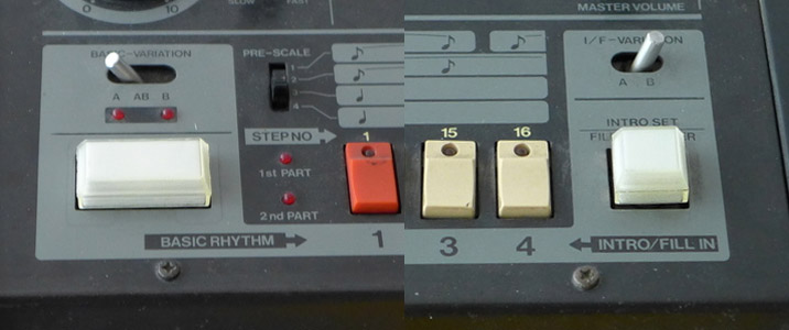
Start / Stop and Tap switches
Updates to this section are at the end.
#SSTap
The above information provides what I consider to be reasonable ways of coping with failure of most of the TR-808's pots and switches which are likely to fail.
#SSTapMrK
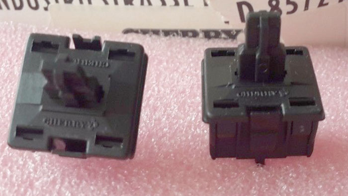
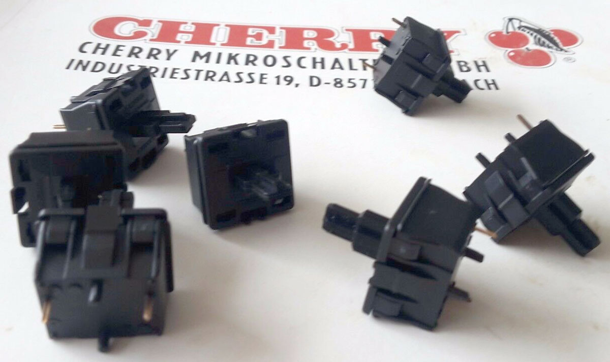
In March 2017 the proprietor of Astro Chicken Records in Berlin informed me about a solution to the switch problem from eBay seller stefankraft in Germany. It consists of a Cherry switch soldered to an adaptor board. So this is similar in principle to the switch part of the solution from Social Entropy (Texas) discussed below. The buttons need to be glued to the shaft of the switch, since its cross-shaped shaft is smaller than the one which the button fits.
I have not experimented with this, but I wonder if hot-melt glue would be suitable. For many years I ignored hot-melt glue, thinking it was cheap and crappy and not very useful. However, it sticks to many thermoplastics better than anything else, except for polystyrene and ABS which can be dissolved with solvents and so properly glued. (Tetrahydrofuran / THF tetra hydro furan works for ABS.) It is easy to apply, works better if the surfaces are pre-heated, and can be easily reworked. Recently I was soldering to some very fine nichrome (I assume) wire from an electric blanket and wanted the joint to be mechanically robust with the insulation of the wires held together, and some hot-melt glue with heatshrink over the top did the job perfectly.
#SSTapSE
2019-03-21: The font I chose and its size are not quite right for matching the original. The characters need to be a little bigger and the line a little thicker. If you come up with a better design, please let me know and I can put the file on this page or link to your page.
Also, since the design is only black, you can probably use a 600DPI laser printer (many now use LED arrays, but are still known as laser printers) on some kind of orange paper or card. I have a report of this working well on some origami paper, but do not yet have the details of where to get this paper.
See below for some Cherry swiches from a Bulgarian eBay seller which do the job well, so I think there is no longer a need to make these PCB adaptors or to create new buttons for these modern Cherry switches. (Of course if the button is lost, then one needs to be made.)
In 2014 there is an important new development: Social Entropy developed a replacement kit for the two switches and their white plastic buttons. This was never made generally available and in 2019 there are no plans to produce this product.
See #update20181120 below for the CAD files for such 3D printed buttons and for where you can purchase.already made up Cherry switches on an adaptor PCB.
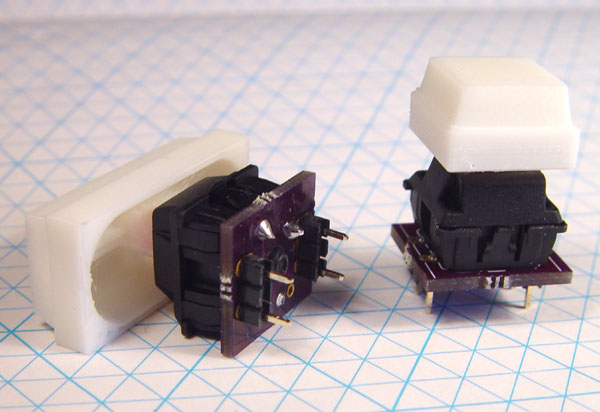
It consists of a modern keyboard switch (by Cherry), soldered to a specially designed PCB with pins, which brings it to the correct height. Since the + pattern of the new switch, where it connects to the button, does not suit the TR-808's white plastic buttons, there is a very well crafted, 3D printed (with the tops and sides precisely milled), white plastic button in place on the switch. (This can be removed from the switch shafts, but there is no need to do so.) The idea is that the orange label and the outer transparent shell from the TR-808 are affixed to the new button.
In February 2014 I installed these in a customer's machine. (Someone had sprayed oil everywhere and this had made the original switches completely non-functional. The outcome was a total success.
This approach is clearly superior to any other solution I know of. I have used them twice since then - likewise, total success.
A machine I worked on in May 2015 had an inactive Run/Stop switch with its shaft broken off, and so no button, orange label or transparent shell to go over these. The Tap switch, button, label and shell was OK. I replaced them both with the Social Entropy kit, plus my own inkjet printed labels.
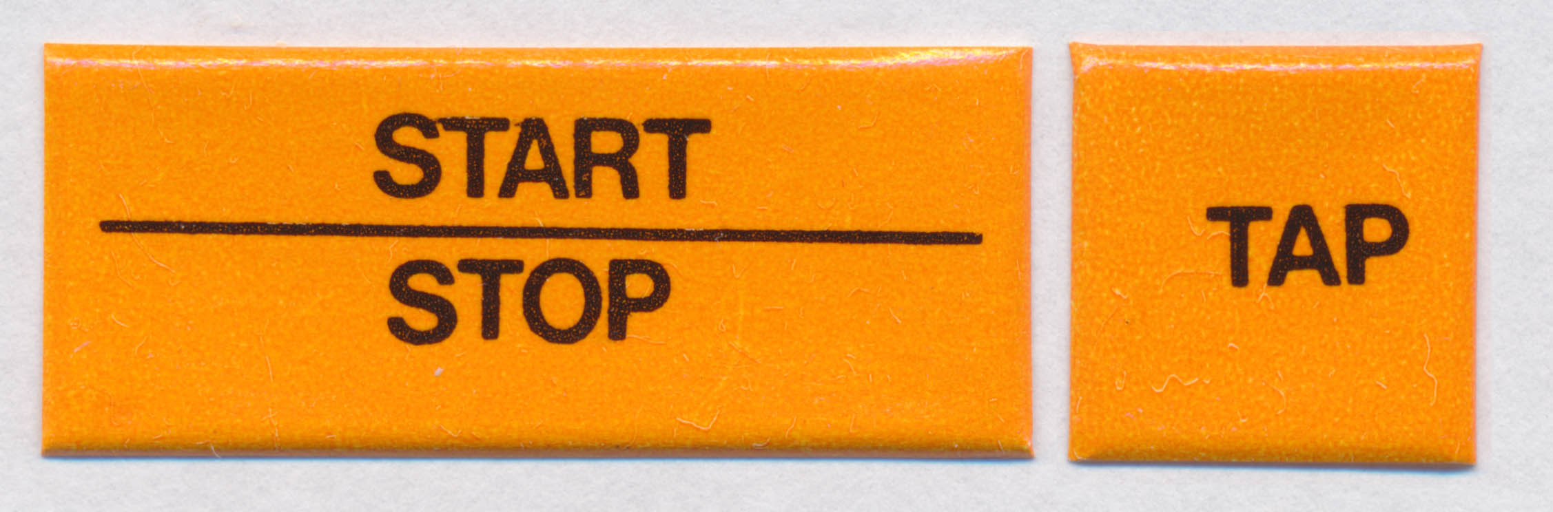
The artwork is done with open-source Inkscape. Here it is: TR-808-orange-labels-Start-Stop-Tap-00.svg
Here is a JPG of the design:
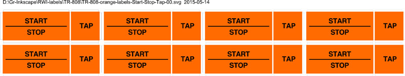
For anyone who wants to do their own design, here is a scan of some original labels, which have not been exposed to light very much: labels-aligned.jpg The original colour is a vibrant orange, not the faded orange of many labels after 34 years of exposure to light.
Here is the result:
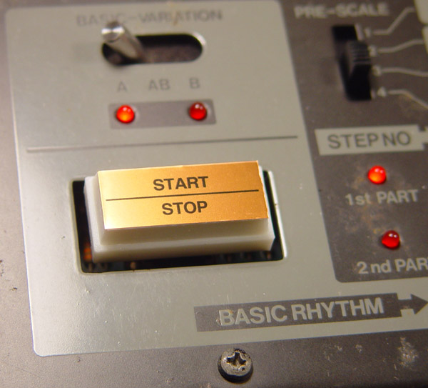
See the next sub-section below for where to get transparent covers / shells / "hulls" for these buttons.
The above Inkscape file can be used to print labels however you like. For those who are interested in my technique, here it is in a subsection below. There's no way I could reproduce the vibrant orange colour of the original labels with the inkjet on this matte silver material. I suspect no inkjet could do it. The trouble is that it is not possible to inkjet print on ordinary paper, such as suitable orange paper, since the ink spreads, or will not sit in the same place and dry quickly, unless the paper has a special inkjet compatible coating. Perhaps a good laser printer would work well on orange paper, in which case it would be necessary to edit the file to delete the orange rectangles.
#shells
#labelprinting
My laminated inkjet printed matte silvery label technique using A-One 29283 material (May 2015)
The following is what I wrote before this SocialEntropy kit became available:
The first subsection here concerns the original switches and how they might be refurbished. In a further subsection below that I consider alternative switches.
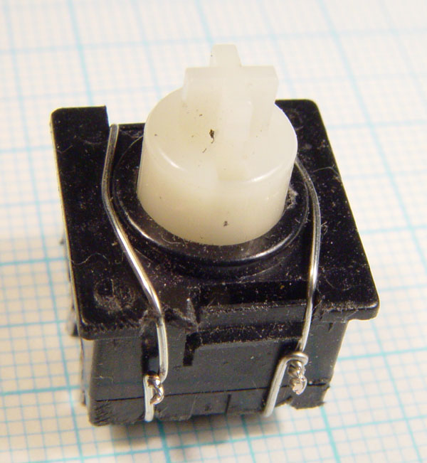
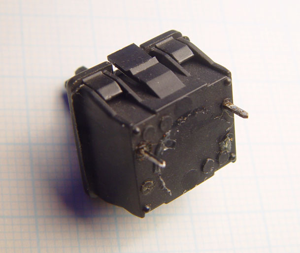
All the switches I have had to replace have been of the type shown immediately below, with a white stem and two melted lugs to hold the switch together. One problem refurbishing these is how to get the switch back together.
Another type has a black shaft and side clips to hold the switch together. If one of these is in a TR-808 (I have not seen one so) then refurbishing these is a lot easier because the switches can be snapped apart and back together with ease. If you are fixing a switch of this latter type, please read the next section on cleaning the contacts, but it will be obvious how to put your switch back together.
The above information provides what I consider to be reasonable ways of coping with failure of most of the TR-808's pots and switches which are likely to fail.
#SSTapMrK
In March 2017 the proprietor of Astro Chicken Records in Berlin informed me about a solution to the switch problem from eBay seller stefankraft in Germany. It consists of a Cherry switch soldered to an adaptor board. So this is similar in principle to the switch part of the solution from Social Entropy (Texas) discussed below. The buttons need to be glued to the shaft of the switch, since its cross-shaped shaft is smaller than the one which the button fits.
The above article has a link to the
eBay item, but these item numbers tend to change over time, so here is
the link to the seller, though the TR-808 switch kits (also for the MC-4) do not appear on this page: http://www.ebay.com/usr/stefanrkraft .
I have not experimented with this, but I wonder if hot-melt glue would be suitable. For many years I ignored hot-melt glue, thinking it was cheap and crappy and not very useful. However, it sticks to many thermoplastics better than anything else, except for polystyrene and ABS which can be dissolved with solvents and so properly glued. (Tetrahydrofuran / THF tetra hydro furan works for ABS.) It is easy to apply, works better if the surfaces are pre-heated, and can be easily reworked. Recently I was soldering to some very fine nichrome (I assume) wire from an electric blanket and wanted the joint to be mechanically robust with the insulation of the wires held together, and some hot-melt glue with heatshrink over the top did the job perfectly.
#SSTapSE
2019-03-21: The font I chose and its size are not quite right for matching the original. The characters need to be a little bigger and the line a little thicker. If you come up with a better design, please let me know and I can put the file on this page or link to your page.
Also, since the design is only black, you can probably use a 600DPI laser printer (many now use LED arrays, but are still known as laser printers) on some kind of orange paper or card. I have a report of this working well on some origami paper, but do not yet have the details of where to get this paper.
See below for some Cherry swiches from a Bulgarian eBay seller which do the job well, so I think there is no longer a need to make these PCB adaptors or to create new buttons for these modern Cherry switches. (Of course if the button is lost, then one needs to be made.)
In 2014 there is an important new development: Social Entropy developed a replacement kit for the two switches and their white plastic buttons. This was never made generally available and in 2019 there are no plans to produce this product.
See #update20181120 below for the CAD files for such 3D printed buttons and for where you can purchase.already made up Cherry switches on an adaptor PCB.
It consists of a modern keyboard switch (by Cherry), soldered to a specially designed PCB with pins, which brings it to the correct height. Since the + pattern of the new switch, where it connects to the button, does not suit the TR-808's white plastic buttons, there is a very well crafted, 3D printed (with the tops and sides precisely milled), white plastic button in place on the switch. (This can be removed from the switch shafts, but there is no need to do so.) The idea is that the orange label and the outer transparent shell from the TR-808 are affixed to the new button.
In February 2014 I installed these in a customer's machine. (Someone had sprayed oil everywhere and this had made the original switches completely non-functional. The outcome was a total success.
This approach is clearly superior to any other solution I know of. I have used them twice since then - likewise, total success.
A machine I worked on in May 2015 had an inactive Run/Stop switch with its shaft broken off, and so no button, orange label or transparent shell to go over these. The Tap switch, button, label and shell was OK. I replaced them both with the Social Entropy kit, plus my own inkjet printed labels.
The artwork is done with open-source Inkscape. Here it is: TR-808-orange-labels-Start-Stop-Tap-00.svg
Here is a JPG of the design:
For anyone who wants to do their own design, here is a scan of some original labels, which have not been exposed to light very much: labels-aligned.jpg The original colour is a vibrant orange, not the faded orange of many labels after 34 years of exposure to light.
Here is the result:
See the next sub-section below for where to get transparent covers / shells / "hulls" for these buttons.
The above Inkscape file can be used to print labels however you like. For those who are interested in my technique, here it is in a subsection below. There's no way I could reproduce the vibrant orange colour of the original labels with the inkjet on this matte silver material. I suspect no inkjet could do it. The trouble is that it is not possible to inkjet print on ordinary paper, such as suitable orange paper, since the ink spreads, or will not sit in the same place and dry quickly, unless the paper has a special inkjet compatible coating. Perhaps a good laser printer would work well on orange paper, in which case it would be necessary to edit the file to delete the orange rectangles.
#shells
3D printed clear covers ("hulls") for these buttons - designed in Vienna
In May 2015, just after I shipped the
TR-808 mentioned above to the customer, I received an email from a
fellow in Vienna who has apparently solved the final problem with these
buttons - he has created both replacement buttons (to match the
original ALPS switch stems) and transparent 3D printed acrylic "hulls"
as he refers to them - covers, or shells - to match these buttons.
I am yet to see one of these, but from all I can tell he has done a good job.
Since these match the original button, and since the Social Entropy button is machined to be the same shape as the original button, so it fits the original shells, I think these new shells will work fine with the Social Entropy buttons.
The buttons and shells can be purchased directly from Shapeways in the USA, who fabricate them.
See #update20181120 below for the CAD files for such 3D printed buttons.
#labelprinting
My laminated inkjet printed matte silvery label technique using A-One 29283 material (May 2015)
Until June 2015 I thought the material
I print onto was only available via Amazon Japan, via another company
who would buy it on my behalf and ship it to Australia. Now it
seems there are multiple Amazon sellers who will ship to Western
countries, so this makes the whole process a lot easier.
I use an Epson Stylus Pro 3800 with Ultrachrome K3 pigment (little particles of solid coloured material, rather than a dye) inks. The Stylus Pro 3880 is more common, and I guess any of the Epson printers which use this ink would produce identical results. (The set of inks for these printers are expensive - they are not domestic cheapies.)
I made a special profile in the Windows driver for printing onto the A-One-Label matte silver material. It involves using the Photo Black ink, rather than the Matte Black:
Obtaining the A-One 29283 material
A-One was purchased by 3M a few years ago. The brand name and product number A-One 29283
Googling for: A-One 29283 was my key to finding this material. Googling, a year or two ago, I found a handful of small retailers in Japan listed it, but none both had it in stock and would ship to Australia. So I decided to get it from Amazon Japan. As far as I knew, it was not possible for me to do this and have them ship the items to Australia.
Therefore, I used another company to purchase ten packs on my behalf, and ship them to Australia. This was a lot of trouble to get some adhesive labels, but it is a superb material, unlike any other I could find. (If some enterprising person decides to retail these on eBay or whatever, for direct delivery to Western countries, please let me know and I will add a link here.)
I used http://www.fromjapan.co.jp/ to purchase and ship the labels. I have only used them for this transaction, and it went very well. They claim to do about 2000 orders a day, so I think they have a highly efficient operation.
By searching http://www.amazon.co.jp (there is now an "In English" option) for 29283 I was able to find these labels. In May 2015, a link for one of these is:
The newer packages have a design with five turquoise panels and a single jar. An earlier package, still used by some sellers, depicts a pasta jar.
In June 2015, thanks to Paul of http://www.punkdisco.co.uk writing on the Synth-DIY mailing list ( http://dropmix.xs4all.nl/mailman/listinfo/synth-diy ) I now know of Amazon sellers, who will deliver A-One 29283 to customers in Western countries. Paul pointed out that this material has an Amazon Standard Identifier Number (ASIN) of B0000ACBQC . He reported that Googling this turned up two such sellers:
At http://www.amazon.com, I simply entered B0000ACBQC into the search box, and then clicked on an option for "More buying options - new" and found a bunch more sellers who would apparently deliver to Western countries.
After printing, it is essential to remove all moisture from the label, before laminating.
I do this with a 240 volt electric frying pan, with a dark grey non-stick surface, running from a large 120V autotransformer, so it doesn't heat up too much before the thermostat turns the heater off. I think it is a 2400 watt frying pan, so at half the voltage it uses 1/4 the power = 600 watts, so this requires a hefty auto-transformer.
I adjust the thermostat carefully and use an infra-red non-contact thermometer to set the temperature in the 105C to 140C region. The temperature is not particularly critical, but it needs to be above the boiling point of water (the Ultrachrome inks are water-based) and not so hot as to distort the plastic label. I place the label printed side up in the frying pan and cover it with a large aluminium pie dish. This means the label will be at exactly the same temperature as the frying pan, but still allows air to move through to carry out the moisture. I generally leave the label there for 15 minutes or so.
A hot air gun, hot air heater or hair dryer would probably work fine too. Likewise an electric oven.
After the label is dried, I laminate it using a standard office supply shop laminator and lamination pouch. In the case of some labels, where I hand-write serial numbers and dates, I do this either with a water-based red fine fibre-tipped pen, or with a solvent-based pen (a fine Sharpie, which are hard to find now). For the water-based pen, I do this before the drying stage.
Then the labels can be cut with a ruler and knife (on a glass surface), a rolling wheel paper cutter or whatever.
The next trick, not needed for these TR-808 button labels, is to round the corners. I do use this for some of the other TR-808 labels For this I use a particular heavy-duty corner cutter. (I tried a Crop-A-Dile cutter and did not like it.) The small radius (2mm) corner cutter has no brand name. I got it from the Oregon Laminations Company:
http://www.oregonlam.com/CR2MM_2mm_3_32_Corner_Rounder_Cutter_Punch.html
though this one might be good too. This company has a vast array of tools and lamination supplies, including corner cutters / corner rounders of various sizes.
The resulting labels are not impervious to water or probably to a high-humidity environment. The hot-melt glue of the lamination material seals well on the unprinted A-One label, and (at least for the Ultrachrome ink I am using) the printed areas too. (I understand that the adhesive most commonly used for lamination films is ethylene-vinyl acetate - the same as used hot melt glue gun sticks.) This is quite an achievement, and it relies on the ink being dry and being well absorbed by whatever inkjet coating is at the top of the A-One material. This good bonding enables the creation of labels with black or coloured backgrounds right to the edge. It is my impression that these are generally quite robust labels for general use on electronic equipment. However, if left out in the rain, some water will get in the edges and change the satin finish to more of a gloss finish. Eventually, I think the whole label would degrade.
Ultrachrome inks have a good reputation for light-fastness. However, I am sure that if they are exposed to lots of light, potentially over many years, especially with a strong UV component, that the colours will fade somewhat.
The material is plastic - it is not aluminium. So it will be relatively easy to cut with a scalpel or craft knife once it is stuck over slots and holes. I haven't tried this yet.
Keeping dust out of the lamination process is a challenge! It may be best to do this stage outdoors, away from household fluff and dust.
Likewise keeping dust out of the surface before sticking it down. One technique is to peel back the backing plastic along one edge of the label by 1 to 2cm, and fold it back sharply, so the exposed adhesive of the label can be placed on the surface. Once this is done and the edge rubbed down firmly, I found I could rub upwards, peeling back the backing plastic at the same time, so that within a second or two of the adhesive being exposed, it would be pressed firmly into position.
This also helps reduce the problem of air bubbles being caught under the label.
I use an Epson Stylus Pro 3800 with Ultrachrome K3 pigment (little particles of solid coloured material, rather than a dye) inks. The Stylus Pro 3880 is more common, and I guess any of the Epson printers which use this ink would produce identical results. (The set of inks for these printers are expensive - they are not domestic cheapies.)
I made a special profile in the Windows driver for printing onto the A-One-Label matte silver material. It involves using the Photo Black ink, rather than the Matte Black:
Media Type: Premium Semigloss Photo Paper
Custom Settings:
Custom Settings:
Print Quality Level: LEVEL 4
Print Quality: SuperFine - 1440x720dpi (but it might be worth trying less than this if ink-running is a problem, as mentioned below)
High Speed: Off
Finest Detail: On
Edge Smoothing: Off
Print Quality: SuperFine - 1440x720dpi (but it might be worth trying less than this if ink-running is a problem, as mentioned below)
High Speed: Off
Finest Detail: On
Edge Smoothing: Off
I will experiment with a longer than
normal (0 seconds) drying time per print head pass (in "Paper
Configuration) since for solid black areas, and I guess with some other
solid ink patterns, the ink is too wet and tends to run together,
leaving some parts not as black as they should be - a somewhat mottled
effect. This is not a problem for these TR-808 labels.
Obtaining the A-One 29283 material
The material I print on was, as far as I knew (until early June 2015), only available in
Japan - and at one seller in Singapore. It is a fine plastic material, with a strong (I guess
permanent) self-adhesive backing, with a matte silver finish. It
is specifically intended for inkjet printing. I think that if it
was passed through a laser printer, it would melt - and it is unlikely
that its electrostatic behaviour would enable a laser printer to
deposit toner successfully.
It comes in packs of 10 A4 sheets. The manufacturer's page is:
It comes in packs of 10 A4 sheets. The manufacturer's page is:
A-One was purchased by 3M a few years ago. The brand name and product number A-One 29283
Googling for: A-One 29283 was my key to finding this material. Googling, a year or two ago, I found a handful of small retailers in Japan listed it, but none both had it in stock and would ship to Australia. So I decided to get it from Amazon Japan. As far as I knew, it was not possible for me to do this and have them ship the items to Australia.
Therefore, I used another company to purchase ten packs on my behalf, and ship them to Australia. This was a lot of trouble to get some adhesive labels, but it is a superb material, unlike any other I could find. (If some enterprising person decides to retail these on eBay or whatever, for direct delivery to Western countries, please let me know and I will add a link here.)
I used http://www.fromjapan.co.jp/ to purchase and ship the labels. I have only used them for this transaction, and it went very well. They claim to do about 2000 orders a day, so I think they have a highly efficient operation.
By searching http://www.amazon.co.jp (there is now an "In English" option) for 29283 I was able to find these labels. In May 2015, a link for one of these is:
The newer packages have a design with five turquoise panels and a single jar. An earlier package, still used by some sellers, depicts a pasta jar.
In June 2015, thanks to Paul of http://www.punkdisco.co.uk writing on the Synth-DIY mailing list ( http://dropmix.xs4all.nl/mailman/listinfo/synth-diy ) I now know of Amazon sellers, who will deliver A-One 29283 to customers in Western countries. Paul pointed out that this material has an Amazon Standard Identifier Number (ASIN) of B0000ACBQC . He reported that Googling this turned up two such sellers:
http://www.amazon.co.uk/A-one-label-inkjet-matte-silver/dp/B0000ACBQC
http://www.amazon.com/A-one-label-inkjet-matte-silver/dp/B0000ACBQC
http://www.amazon.com/A-one-label-inkjet-matte-silver/dp/B0000ACBQC
At http://www.amazon.com, I simply entered B0000ACBQC into the search box, and then clicked on an option for "More buying options - new" and found a bunch more sellers who would apparently deliver to Western countries.
After printing, it is essential to remove all moisture from the label, before laminating.
I do this with a 240 volt electric frying pan, with a dark grey non-stick surface, running from a large 120V autotransformer, so it doesn't heat up too much before the thermostat turns the heater off. I think it is a 2400 watt frying pan, so at half the voltage it uses 1/4 the power = 600 watts, so this requires a hefty auto-transformer.
I adjust the thermostat carefully and use an infra-red non-contact thermometer to set the temperature in the 105C to 140C region. The temperature is not particularly critical, but it needs to be above the boiling point of water (the Ultrachrome inks are water-based) and not so hot as to distort the plastic label. I place the label printed side up in the frying pan and cover it with a large aluminium pie dish. This means the label will be at exactly the same temperature as the frying pan, but still allows air to move through to carry out the moisture. I generally leave the label there for 15 minutes or so.
A hot air gun, hot air heater or hair dryer would probably work fine too. Likewise an electric oven.
After the label is dried, I laminate it using a standard office supply shop laminator and lamination pouch. In the case of some labels, where I hand-write serial numbers and dates, I do this either with a water-based red fine fibre-tipped pen, or with a solvent-based pen (a fine Sharpie, which are hard to find now). For the water-based pen, I do this before the drying stage.
Then the labels can be cut with a ruler and knife (on a glass surface), a rolling wheel paper cutter or whatever.
The next trick, not needed for these TR-808 button labels, is to round the corners. I do use this for some of the other TR-808 labels For this I use a particular heavy-duty corner cutter. (I tried a Crop-A-Dile cutter and did not like it.) The small radius (2mm) corner cutter has no brand name. I got it from the Oregon Laminations Company:
http://www.oregonlam.com/CR2MM_2mm_3_32_Corner_Rounder_Cutter_Punch.html
though this one might be good too. This company has a vast array of tools and lamination supplies, including corner cutters / corner rounders of various sizes.
The resulting labels are not impervious to water or probably to a high-humidity environment. The hot-melt glue of the lamination material seals well on the unprinted A-One label, and (at least for the Ultrachrome ink I am using) the printed areas too. (I understand that the adhesive most commonly used for lamination films is ethylene-vinyl acetate - the same as used hot melt glue gun sticks.) This is quite an achievement, and it relies on the ink being dry and being well absorbed by whatever inkjet coating is at the top of the A-One material. This good bonding enables the creation of labels with black or coloured backgrounds right to the edge. It is my impression that these are generally quite robust labels for general use on electronic equipment. However, if left out in the rain, some water will get in the edges and change the satin finish to more of a gloss finish. Eventually, I think the whole label would degrade.
Ultrachrome inks have a good reputation for light-fastness. However, I am sure that if they are exposed to lots of light, potentially over many years, especially with a strong UV component, that the colours will fade somewhat.
The material is plastic - it is not aluminium. So it will be relatively easy to cut with a scalpel or craft knife once it is stuck over slots and holes. I haven't tried this yet.
Keeping dust out of the lamination process is a challenge! It may be best to do this stage outdoors, away from household fluff and dust.
Likewise keeping dust out of the surface before sticking it down. One technique is to peel back the backing plastic along one edge of the label by 1 to 2cm, and fold it back sharply, so the exposed adhesive of the label can be placed on the surface. Once this is done and the edge rubbed down firmly, I found I could rub upwards, peeling back the backing plastic at the same time, so that within a second or two of the adhesive being exposed, it would be pressed firmly into position.
This also helps reduce the problem of air bubbles being caught under the label.
The following is what I wrote before this SocialEntropy kit became available:
The first subsection here concerns the original switches and how they might be refurbished. In a further subsection below that I consider alternative switches.
All the switches I have had to replace have been of the type shown immediately below, with a white stem and two melted lugs to hold the switch together. One problem refurbishing these is how to get the switch back together.
Another type has a black shaft and side clips to hold the switch together. If one of these is in a TR-808 (I have not seen one so) then refurbishing these is a lot easier because the switches can be snapped apart and back together with ease. If you are fixing a switch of this latter type, please read the next section on cleaning the contacts, but it will be obvious how to put your switch back together.
Refurbishing the existing switches - melted lug sealing
#Tap-refurb
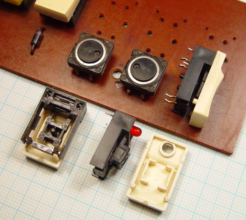
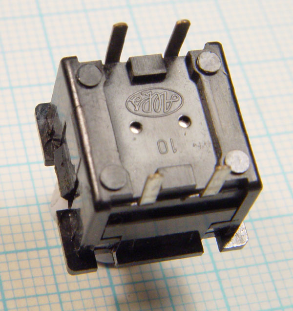
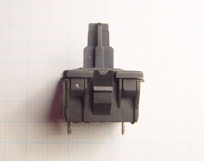
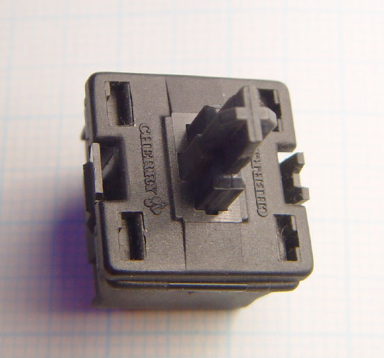
Here are some photo of original switches. It is made by ALPS but I don't know its part number. I don't know of any replacement buttons either, but generally these are not damaged, destroyed or lost.
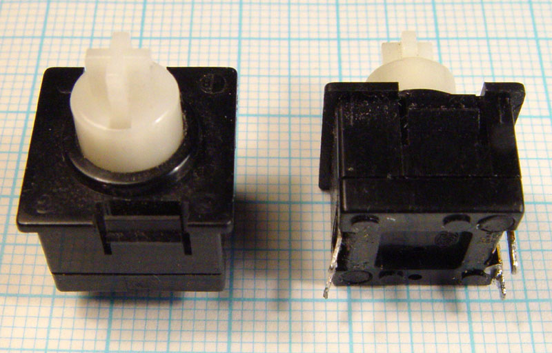
It is possible that later TR-808s had a different type of ALPS switch with the same dimensions, but a different form of construction, as described below. For simplicity I will refer to the above type as the "original switches".
The key point about them is that the top of the body is affixed to the bottom part, the bottom 3.5mm, by two heat-melted cylindrical lugs. We need to "drill these out" to dismantle the switch, though in the past I recall I cut the switch apart with a knife, which was a bad idea.
I used a small Dremel tool to cut away the ends of the melted lugs. It doesn't take much, just a fraction of a millimetre, before the switch can be prised apart with a knife-blade in the split. By cutting a circular path following where the lug has been melted sideways a little, it is possible to leave the centre of the lug intact, but still cut away enough of its widened end to make it possible to prise the switch apart.
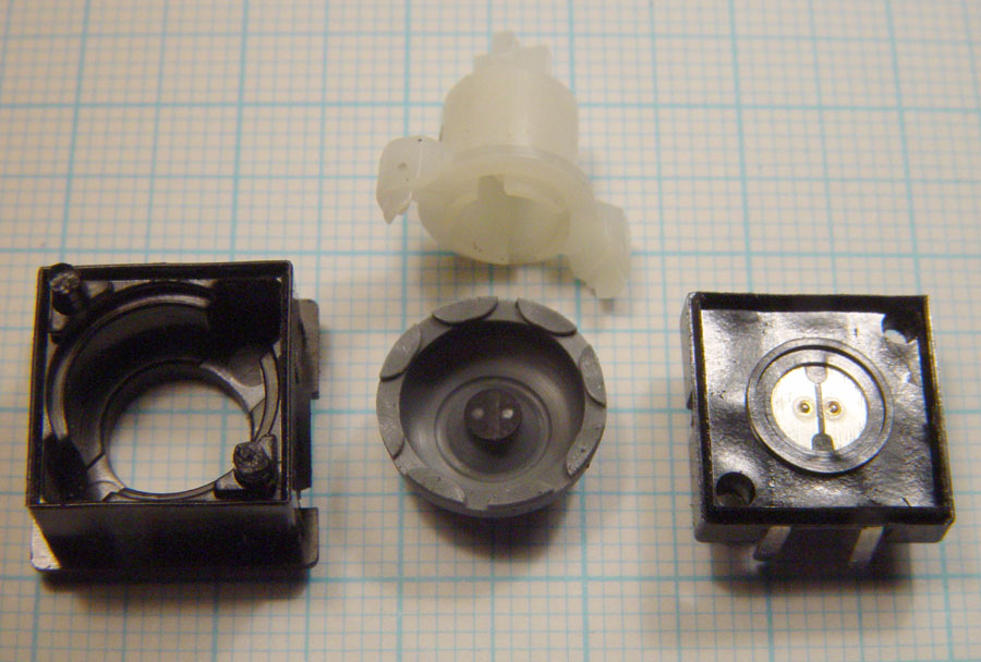
The failure mechanism is the lack of conductivity when the conductive rubber presses against the metal contacts. One of these switches was 127k ohms when pressed. It needs to be about 10k or less to activate the circuit.
My usual approach to dealing with rubber contacts is:
Scratching with a needle cuts through this to the gold and copper below. The 240 grit emery paper scratched up the surface revealing (under the microscope at 30x) some copper rather than gold. This is not ideal, since the copper is subject to corrosion. Still, it is better than retaining whatever coating had built up on the gold surface. When I used 800 grit emery paper, very lightly, under the stereo zoom microscope, I was able to get a gold-looking set of scratches, without obvious copper colour.
An additional step which is possible with these switches is to rotate the rubber cup so that fresh material is exposed to the raised contacts. However, once the conductive rubber is sanded, it is not obvious where it was pressing into the contacts.
Using these techniques I was able to make one of these switches go consistently below 1k ohms - 800 to 900 ohms. However, the other was 2k to 3k and went higher, beyond 10k, as I attempted improvements, such as smoothing down the abraded metal contacts. I assume the rubber contact material has degenerated in some way, perhaps due to some solvent which might have been on contact with it. However, perhaps my abrasion was too rough.
There are some special paints which are intended to fix problems with these conductive rubber switches. I haven't used any and I don't at present know which ones are well-regarded, but such a product might save the second switch. A quick search found this product: http://www.keypadrepair.com .
Also, it would be possible to modify the circuit so it was acceptable to have a 10k or higher resistance.
Assuming the switch contacts can be made to work acceptably, this still leaves a problem with how to fix the switch back together. One approach is to use a soldering iron to melt the lugs again. This would probably work, but next time the switch needs to be refurbished, it will be difficult to do this again.
In the past I tried epoxying these switches together, but that was after a careless disassembly which I think involved cutting around the seam of the switch. I buttressed the sides with epoxy with a filler, going down to the PCB, but still the switches fell apart after a little use.
Here is a method I devised in March 2012 which I think will work well.
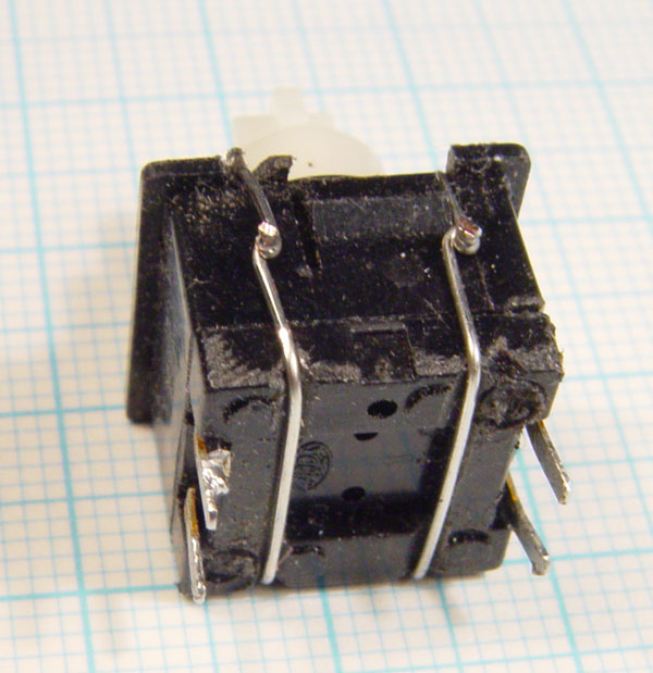
I would solder the twisted joints and probably give them a bit more of a twist to tighten them up further.
This looks a bit rough, but I think it will be strong enough for long-term use. It is easy to pull it apart in the future. Although I filed slots in the bottom, the wire is below the base of the switch so some care or insulation tape or the like will be required when mounting the switch in the TR-808.
Here are some photo of original switches. It is made by ALPS but I don't know its part number. I don't know of any replacement buttons either, but generally these are not damaged, destroyed or lost.
It is possible that later TR-808s had a different type of ALPS switch with the same dimensions, but a different form of construction, as described below. For simplicity I will refer to the above type as the "original switches".
The key point about them is that the top of the body is affixed to the bottom part, the bottom 3.5mm, by two heat-melted cylindrical lugs. We need to "drill these out" to dismantle the switch, though in the past I recall I cut the switch apart with a knife, which was a bad idea.
I used a small Dremel tool to cut away the ends of the melted lugs. It doesn't take much, just a fraction of a millimetre, before the switch can be prised apart with a knife-blade in the split. By cutting a circular path following where the lug has been melted sideways a little, it is possible to leave the centre of the lug intact, but still cut away enough of its widened end to make it possible to prise the switch apart.
The failure mechanism is the lack of conductivity when the conductive rubber presses against the metal contacts. One of these switches was 127k ohms when pressed. It needs to be about 10k or less to activate the circuit.
My usual approach to dealing with rubber contacts is:
- Use some light, clean, fresh, emery paper (dark-grey paper-backed
abrasive sheet) to abrade away the surface of the conductive
rubber. (I don't put any solvents on this, because once when I
did, the rubber became less conductive.) 240 or 400 grit is
probably a good choice.
- Use isopropyl alcohol to clean the metal contacts.
- Maybe
use a very light touch of fine, fresh, emery paper to roughen the
surface of the contact points just a little. 800 grit is probably
a good choice.
Scratching with a needle cuts through this to the gold and copper below. The 240 grit emery paper scratched up the surface revealing (under the microscope at 30x) some copper rather than gold. This is not ideal, since the copper is subject to corrosion. Still, it is better than retaining whatever coating had built up on the gold surface. When I used 800 grit emery paper, very lightly, under the stereo zoom microscope, I was able to get a gold-looking set of scratches, without obvious copper colour.
An additional step which is possible with these switches is to rotate the rubber cup so that fresh material is exposed to the raised contacts. However, once the conductive rubber is sanded, it is not obvious where it was pressing into the contacts.
Using these techniques I was able to make one of these switches go consistently below 1k ohms - 800 to 900 ohms. However, the other was 2k to 3k and went higher, beyond 10k, as I attempted improvements, such as smoothing down the abraded metal contacts. I assume the rubber contact material has degenerated in some way, perhaps due to some solvent which might have been on contact with it. However, perhaps my abrasion was too rough.
There are some special paints which are intended to fix problems with these conductive rubber switches. I haven't used any and I don't at present know which ones are well-regarded, but such a product might save the second switch. A quick search found this product: http://www.keypadrepair.com .
Also, it would be possible to modify the circuit so it was acceptable to have a 10k or higher resistance.
Assuming the switch contacts can be made to work acceptably, this still leaves a problem with how to fix the switch back together. One approach is to use a soldering iron to melt the lugs again. This would probably work, but next time the switch needs to be refurbished, it will be difficult to do this again.
In the past I tried epoxying these switches together, but that was after a careless disassembly which I think involved cutting around the seam of the switch. I buttressed the sides with epoxy with a filler, going down to the PCB, but still the switches fell apart after a little use.
Here is a method I devised in March 2012 which I think will work well.
I would solder the twisted joints and probably give them a bit more of a twist to tighten them up further.
This looks a bit rough, but I think it will be strong enough for long-term use. It is easy to pull it apart in the future. Although I filed slots in the bottom, the wire is below the base of the switch so some care or insulation tape or the like will be required when mounting the switch in the TR-808.
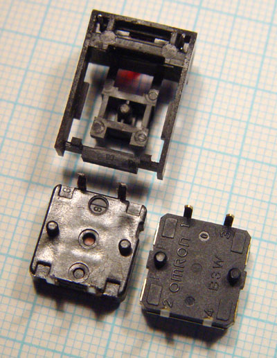
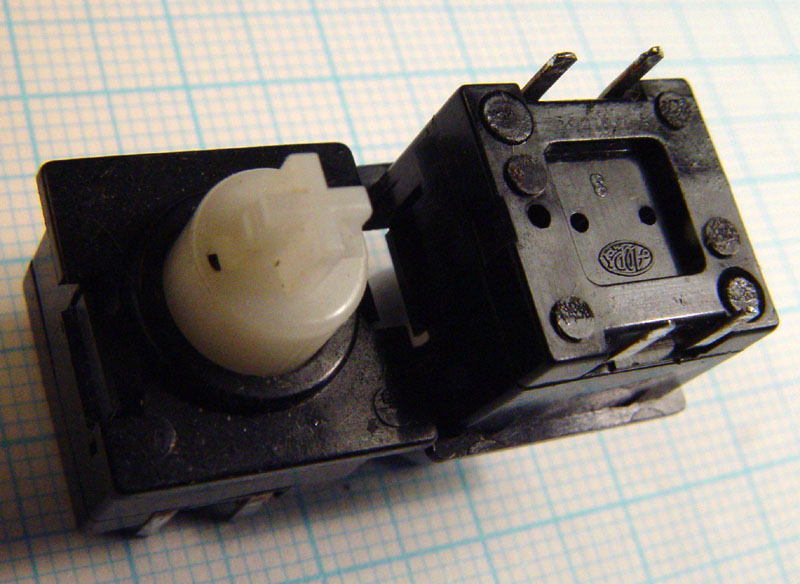
Replacement switch from an MC-4
#Tap-side-clip
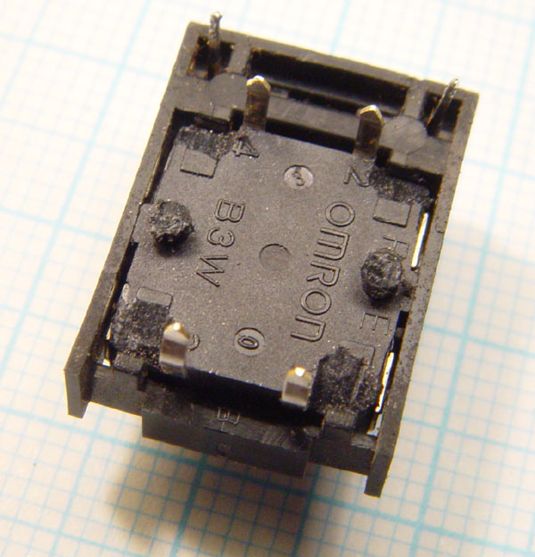
I was lucky enough to obtain a few of these switches, which have never been used used, as spare-parts for the keyswitch panel of an MC-4 micro-composer. These are physically compatible with the switches above, and perhaps they are used on some TR-808s.
They operate on the same principles, so refurbishing the contacts would be along the lines described above.
This one had a resistance of about 500 ohms.
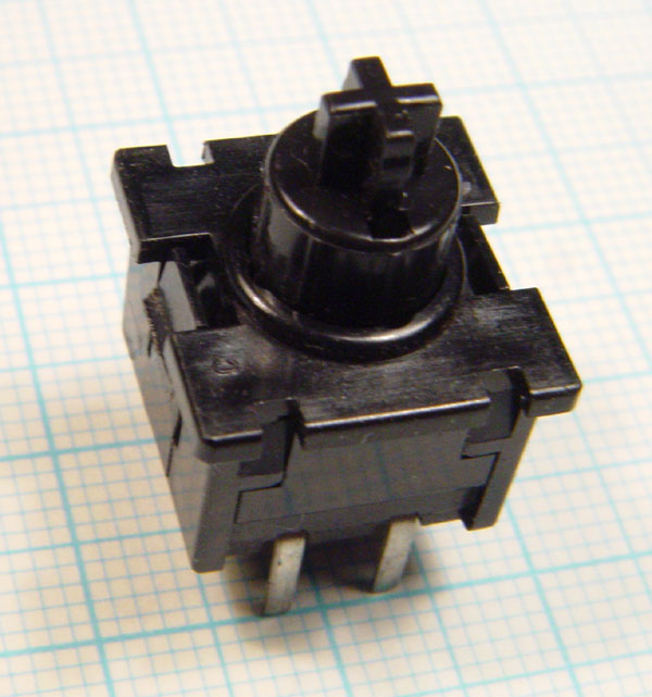
Both types of switch are intended to snap into a punched steel plate for the purposes of making a numeric, QUERTY or other similar kind of "keyboard" set of switches.
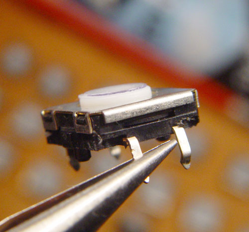
The sides unclip easily to reveal:
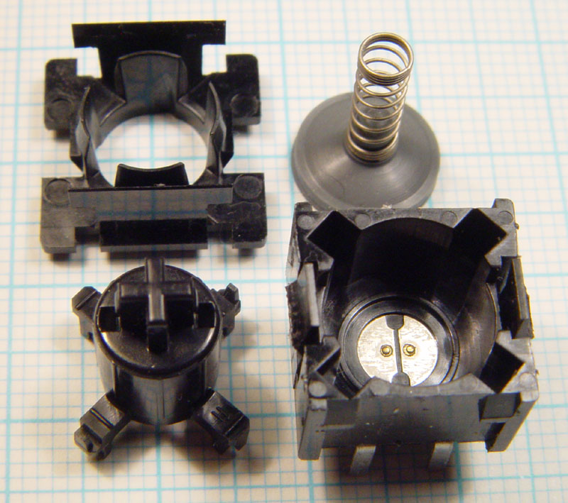
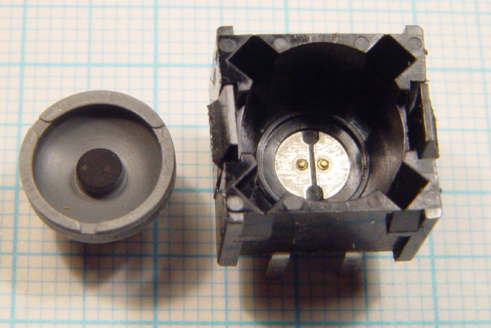
I believe these are a later model, superior, switch to the melted lug version. The melted lug version used deformation of the silicone rubber cup to take up the slack of the button moving down past the point where the contacts closed. This one uses a coil spring, and I believe this places less stress on the silicone rubber cup.
Does anyone know a source of these switches or anything like them?
I was lucky enough to obtain a few of these switches, which have never been used used, as spare-parts for the keyswitch panel of an MC-4 micro-composer. These are physically compatible with the switches above, and perhaps they are used on some TR-808s.
They operate on the same principles, so refurbishing the contacts would be along the lines described above.
This one had a resistance of about 500 ohms.
Both types of switch are intended to snap into a punched steel plate for the purposes of making a numeric, QUERTY or other similar kind of "keyboard" set of switches.
The sides unclip easily to reveal:
I believe these are a later model, superior, switch to the melted lug version. The melted lug version used deformation of the silicone rubber cup to take up the slack of the button moving down past the point where the contacts closed. This one uses a coil spring, and I believe this places less stress on the silicone rubber cup.
Does anyone know a source of these switches or anything like them?
Purchasing alternatives?
#Tap-alt
Other than the above mentioned MrK kit and the (perhaps not available) Social Entropy kit, which seems to be an excellent solution, I don't know of any alternative switches. In a July 2011 discussion:
this switch http://www.smallbearelec.com/Detail.bok?no=36 was suggested, but it only has two pins and is apparently a different height.
It can be safely assumed that the people at Technology Transplant (this company no longer exists as far as I know since about 2016) had a better idea of what is manufactured, and can be manufactured, than most folks. Yet they had no such switches. I think this is strong evidence that no such switches are currently being manufactured.
Does anyone have suggestions?
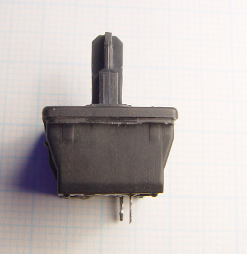
These switches measure 13.5 x 13.5mm in the main body - this is the size of hole they are intended to be mounted in.
The four pins are spaced identically to the ALPS and Omron switches. I was tempted to think of some adaptation of the existing body and slider mechanism with an Omron tact switch replacing the current base of the switch. Another idea is to keep the existing switch body and base, but have a hole through the bottom of it and the PCB, with a shaft driving an Omron switch mounted below the PCB.
Other than the above mentioned MrK kit and the (perhaps not available) Social Entropy kit, which seems to be an excellent solution, I don't know of any alternative switches. In a July 2011 discussion:
this switch http://www.smallbearelec.com/Detail.bok?no=36 was suggested, but it only has two pins and is apparently a different height.
It can be safely assumed that the people at Technology Transplant (this company no longer exists as far as I know since about 2016) had a better idea of what is manufactured, and can be manufactured, than most folks. Yet they had no such switches. I think this is strong evidence that no such switches are currently being manufactured.
Does anyone have suggestions?
These switches measure 13.5 x 13.5mm in the main body - this is the size of hole they are intended to be mounted in.
The four pins are spaced identically to the ALPS and Omron switches. I was tempted to think of some adaptation of the existing body and slider mechanism with an Omron tact switch replacing the current base of the switch. Another idea is to keep the existing switch body and base, but have a hole through the bottom of it and the PCB, with a shaft driving an Omron switch mounted below the PCB.
Update
2018-11-20: Mystery Cherry keyswitch, original ALPS switches from
System J Synthesizers and PCB and 3D printing files from minisystem